Factory (style) Fog Light Switch- Fits knock-out!

But if I'm tapping into the Factory ground for the dimming capability, then the Rigid ground isn't needed, right? Or should I wire them together and then in?

You still need the chassis ground to support the actual (load) lighting; which can draw ten Amps or more, depending on what you're installing. The Dimmer dial Gnd is for Pilot duty ONLY or fractional ampere duty! If you tried to run your lights through that dimmer circuit, you'd destroy the Main body ECU COMPU NETWORK.

So just to be clear... attach the Ridged wire harness (Battery term end) to the NEG and POS battery terminals. Attach the A.O.B. switch's Illumination circuit ground wire to the dimmer dial (Gray wire) ground wire in the dash! ...Make sense? If not hit me back, Cheers!
 
But [MENTION=81322]barryhiram[/MENTION] said
If you want switch light to dim with dash lights, refer to post #37. Dimming function is through the ground wire, so black wire from switch would connect to gray wire (-) at factory harness. Blue wire from switch would connect to green wire (+) at factory harness per attached diagram.

So I got the impression that I definitely need to ground my switch to the gray wire to dim it with the Dimmer switch and lights, etc.

But doesn't the Rigid LED need to be grounded as well?

Wow. If there was a shop in Sacramento, I would just pay to have this done. I have money. I do not have the knowledge, time, or patience. This is turning into a real isht show. I can't believe no one else on the forum has had this exact Rigid to AoB issue with a dimmer issue!
 
Haha! Relax a little, I believe you're over thinking it a bit hahaha!

"...So I got the impression that I definitely need to ground my switch to the gray wire to dim it with the Dimmer switch and lights, etc.

YES! ...that's right; provided you choose one of the factory dash switches that are on the dimmer accessory circuit... RSCA, wiper/side-view mirror heater, temperature control panel, seat heater dials (Toyota option). Choose one of these, locate the Gray wire on that switch and connect it to the Black wire on the A.O.B. switch; this will facilitate the dimmer feature. Connect the Blue wire on the switch to the green wire (illumin circuit) in the dash. Connect the Green wire on the switch (power input) to your power supply e.g., headlights, parking lights, cigarette lighter...etc. And connect the Red wire (Output to Rly) from the switch to your relay wire (terminal 86) in the Ridged harness... and that's it, YOUR DONE!

PS: If you use the dimmer dial ground (Gray wire), then you can Ignore 'Ridged's' GND wire that was supplied (for convenience) to connect to your light switch in the vehicle.

"But doesn't the Rigid LED need to be grounded as well?"

Yes. You'll connect the other end of the Ridged harness directly to the battery which will feed the LED; there should be an in-line fuse on the POS harness wire connector... and connect the Black wire on the harness to the NEG battery post.

...See how easy that was lol! Cheers!
 
Last edited:
Ok, hopefully I can clear this up for you [MENTION=46530]4Funnr[/MENTION], you have two items you’re trying to interface, AOB dash switch, and Rigid light with harness

AOB switch has two components to it, first is illumination (back lighting) of switch, when headlights are on it would allow you to see the switch at night even though your light bar is off. Switch wire colors are BLACK & BLUE interfaced into factory wires Gray & Green (as I’ve already posted). Illumination is optional, just depends on what you like.

Second component, is switch function - ON/OFF! This is the fun part; you need to decide how you want the light bar to turn on/off. Do you want to be able to turn on your light anytime with engine off, only when the ignition is on, or when your parking/headlights are on? The GREEN wire is the input to the switch and in this case must be a 12 volt source (+). If you desire light any time, connect to a constant power supply (battery) or red wire of Rigid switch harness. If you desire ignition, connect to a source that goes to 12 volts when the ignition is turned on (turn engine off, light bar turns off). Lastly (in this case) parking lights/headlights, connect to a source that goes to 12 volts when you turn on your lights. Remaining wire on switch is RED, this is your output or trigger wire to the Rigid relay (terminal #86) when you turn AOB switch on. When you depress switch to turn it on, the second LED (top half of switch) will light to indicate light bar is on (as long as your input source is on). At this point the AOB switch is just a triggering switch to the relay and will only draw milliamps (low current).

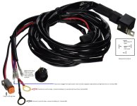
Now for part 2 of 2 – the RELAY! Below is a picture of your harness (I believe) and what wires you need to hookup. Blue (terminal #86) is the input wire/trigger to relay from red wire on AOB switch. Red (with inline fuse, terminal #30) and Black (terminal #85) wires with larger ring terminals should connect directly to the battery. Why, because when you turn on your dash switch, it triggers the relay (through its internal coil) and latches relay so lights are drawing directly off battery not switch, relay handles the load. I’ve also added a relay terminal diagram to the picture, if you have problems identifying wires, unplug relay from socket, you will see numbers stamped on the bottom of relay next to each terminal. Then trace each wire to identify what’s what. There are many different uses and configurations for relays, what is described here is the most popular. Hope it helped!
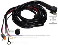
Rigid Harness2.jpg

Thanks for all your input [MENTION=83083]rigtec[/MENTION]……………..buddy & pal!

 

Attachments

  • Rigid Harness2.jpg
    Rigid Harness2.jpg
    114.6 KB · Views: 4,308
Thanks [MENTION=81322]barryhiram[/MENTION] and [MENTION=83083]rigtec[/MENTION].

The last illustration you posted is incredibly helpful and now I actually understand what's going on and how to check my relays to make sure they match.

I also need to check my factory OEM harnesses because my dimmer has four wires, including the gray and green, but my RSCA didn't seem to have gray and green.

How do you guys normally tap/splice into the OEM wires? Would a ScotchLock aka Splice Connector aka Plier Tap work fine for the gray and green OEM wires?

ni75837-2ol.jpg
 
Thanks [MENTION=81322]barryhiram[/MENTION] and [MENTION=83083]rigtec[/MENTION].

The last illustration you posted is incredibly helpful and now I actually understand what's going on and how to check my relays to make sure they match.

I also need to check my factory OEM harnesses because my dimmer has four wires, including the gray and green, but my RSCA didn't seem to have gray and green.

How do you guys normally tap/splice into the OEM wires? Would a ScotchLock aka Splice Connector aka Plier Tap work fine for the gray and green OEM wires?

ni75837-2ol.jpg

Welcome!

Although T-Taps and Scotch Locks are easy to use, they do not provide a good connection as they cut into the wire, this will lead to an intermittent connections…………..sometimes your lights will work, sometimes they won’t………..wiggle the harness and all of a sudden they’ll work again. I prefer to strip the wire insulation back, twist the connecting wire around it then solder the two together. Wrap with quality electrical tape (3M Super-88) to protect connection from shorting on any other component, then cover with wire loom…..one and done! For exterior connections always use heat shrink tubing to prevent corrosion.

For dash lighting interface, there are several dash switches to the left of steering wheel that should have the correct wires. As mentioned before, always test wiring with a voltmeter for proper operation prior to making any connection!!!!!!!!!!!!!!
 
[MENTION=81322]barryhiram[/MENTION]

Is using a multimeter as simple as stripping the green OEM wire and then touching the red positive from the multimeter to it while touching the black ground from the multimeter to bare metal?

I am worried that having a stripped wire exposed while the battery is still connected would carry a risk of shock if I touch it? Not sure how you experts reconcile this?

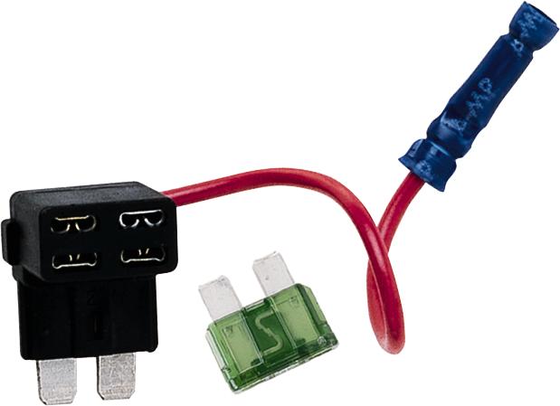
And how do you feel about fuse taps? Presumably I could just tap into a fuse for headlights under the driver dash with the fuse box and use that to connect to the AoB switch green wire?

buss_fuse_tap.jpg
 
Last edited:
Hi [MENTION=46530]4Funnr[/MENTION],

As far as splicing into the truck's Illumination circuit, I just cut the Green wire on the RSCA button. I stripped the insulation from the wire, joined my new wire (to be used as the illumin feed to my A.O.B. SW), and then used a crimp connector (Stake-on) to rejoin the Green wire that I cut into; I did NOT use the Gray wire (Dimmer dial), but instead, a Gnd wire from my PIAA foglight harness, which provides NO dimming. Here's a diagram of the illumin circuit below:


See at the bottom circled in purple trace; on the extreme right (Blue arrow) is the Curtain airbag cut-off SW.(RSCA); it shows two wires (Green [+] and Gray [-]) that pertain to the illumination circuit... I'm almost certain that your truck's wiring yields the very same color coding as all other 5'th gen 4Runners so perhaps take another look. Best to you!
 
Is using a multi-meter as simple as stripping the green OEM wire and then touching the red positive from the multimeter to it while touching the black ground from the multimeter to bare metal?

I am worried that having a stripped wire exposed while the battery is still connected would carry a risk of shock if I touch it?

No need for concern... A 12 volt dc power supply isn't high enough to overcome the electrical resistance needed to travel through the body. Perhaps if you were soaking wet, you may be able to detect a slight tingle, but certainly not enough to cause harm. The reason you should use a volt meter is just a precaution to avoid cutting into a wire that doesn't pertain to the circuit of interest. It can also prevent creating a short circuit by mistake e.g., HOT to GND. If your wiring diagram instructs you that, let's say... a Gray wire is ground, then placing a volt meter between your battery's POS feed and that Gray wire, should reveal 12.5 volts on the display... Make sense? :thumb:
And how do you feel about fuse taps? Presumably I could just tap into a fuse for headlights under the driver dash with the fuse box and use that to connect to the AoB switch green wire?

You could do that to assign power supply to your AOB switch, but that wouldn't provide ON/OFF switching from the headlight stalk; fuse is Hot At All Times, so you'd risk an opportunity that could leave the new lighting on after you've parked; should be a Fail Safe power source!
 
Last edited:
No need for concern... A 12 volt dc power supply isn't high enough to overcome the electrical resistance needed to travel through the body. Perhaps if you were soaking wet, you may be able to detect a slight tingle, but certainly not enough to cause harm. The reason you should use a volt meter is just a precaution to avoid cutting into a wire that doesn't pertain to the circuit of interest. It can also prevent creating a short circuit by mistake e.g., HOT to GND. If your wiring diagram instructs you that, let's say... a Gray wire is ground, then placing a volt meter between your battery's POS feed and that black wire, should reveal 12.5 volts on the display... Make sense? :thumb:


You could do that to assign power supply to your AOB switch, but that wouldn't provide ON/OFF switching from the headlight stalk; fuse is Hot At All Times, so you'd risk an opportunity that could leave the new lighting on after you've parked; should be a Fail Safe power source!

^^^^ what he said^^^^ :bigok:

Is using a multimeter as simple as stripping the green OEM wire

Purpose of meter is to test wires BEFORE cutting/stripping. You could A) unplug factory switch and test at plug, or B) take your probe and test on the back side of plug (without removing switch). Since wires are of small gauge, using a paperclip or pin would allow easier access into factory connector.

Butt connectors and fuse taps are all acceptable means to splice/connect wires............like I said, I prefer to solder my connections when ever possible.

When installing my light bar I wired it to a battery feed (all time power) because it has a strobe feature built-in. As far as leaving to light bar on when departing vehicle, I rarely use the dash switch, plus this thing is friggin' bright, no chance of leaving it on! One thing I recommend (in the future, once you get everything working correctly....lol) is to tie relay into high beam circuit, turn on high beams, light bar turns on automatically.........can you say "daytime":reddance:

Good luck on your install (it's really not that complicated), and post some pictures when your done!
 
Rigid Harness2.jpg

Almost forgot to mention, unused red wire in Rigid switch harness will have 12 volts all the time (HOT)! If your not using it, would recommend removing it from bottom of relay or at least insulate it so it can't short on any metal behind dash panel.
 

Attachments

  • Rigid Harness2.jpg
    Rigid Harness2.jpg
    114.6 KB · Views: 1,802
[MENTION=81322]barryhiram[/MENTION]
Thanks. I think I've got it mostly figured out thanks to you and [MENTION=83083]rigtec[/MENTION]. I fly back into town Saturday and will probably spend my weekend working on it.

I know many people prefer to wire these to their high beams but I'm a biologist and do a lot of road cruising on desolate roads. I was planning to use my Rigid bar + Factory Low Beams + Factory Fog Lights to get as much light as possible to watch the creepy crawlies on the road. If I tie them to my high beams, I lose a lot of 'close and wide' light that's pretty useful.

Hell, I'll probably just leave the LED wired independent for a while. May get some wear and tear on the switch with oncoming cars but at least the switch is easily replaced because it has an AoB harness on the back that plugs in.

But if one were interested, where could I find the high beam or low beam circuits to tie the relay into? And would this have to be done under hood at the relay? Or in dash at the switch with the green wire?
 
Last edited:
Wow. If there was a shop in Sacramento, I would just pay to have this done. I have money. I do not have the knowledge, time, or patience. This is turning into a real isht show. I can't believe no one else on the forum has had this exact Rigid to AoB issue with a dimmer issue!

I think now you understand why I went the easy route and didn't tap any factory wires up front. Just used rigid harness and AOB switch, dimming is overrated.

:peace:
 
[MENTION=81322]barryhiram[/MENTION]
Thanks. I think I've got it mostly figured out thanks to you and [MENTION=83083]rigtec[/MENTION]. I fly back into town Saturday and will probably spend my weekend working on it.

I know many people prefer to wire these to their high beams but I'm a biologist and do a lot of road cruising on desolate roads. I was planning to use my Rigid bar + Factory Low Beams + Factory Fog Lights to get as much light as possible to watch the creepy crawlies on the road. If I tie them to my high beams, I lose a lot of 'close and wide' light that's pretty useful.

Hell, I'll probably just leave the LED wired independent for a while. May get some wear and tear on the switch with oncoming cars but at least the switch is easily replaced because it has an AoB harness on the back that plugs in.

But if one were interested, where could I find the high beam or low beam circuits to tie the relay into? And would this have to be done under hood at the relay? Or in dash at the switch with the green wire?

Cool, it's all about your intended use! We're not concerned with creepy crawlies on the road, moose are another thing! Generally hitting a 2000 lbs. moose at highway speeds does not turn out well........for the moose or you, thus high beam interface.

If you were to interface high or low beams, make it under the hood , they make wire harness extensions.............

H11 Harness extension - 2 Piece H8/H9/H11 Extension Adapter Wiring Harness Sockets Wire Cable for Headlight - Extension Cords - Amazon.com
9005 Harness extension - Amazon.com: iJDMTOY 9005 HB3 9145 H10 Extension Wiring Harness Sockets: Automotive

Using these you just unplug connector at headlight bulb, plug in extension, make your splice in the extension, reconnect to headlight bulb. You haven't affected factory harness in anyway and it's 100% reversible!
 
Last edited:
Cool, it's all about your intended use! We're not concerned with creepy crawlies on the road, moose are another thing! Generally hitting a 2000 lbs. moose at highway speeds does not turn out well........for the moose or you, thus high beam interface.

If you were to interface high or low beams, make it under the hood , they make wire harness extensions.............

H11 Harness extension - 2 Piece H8/H9/H11 Extension Adapter Wiring Harness Sockets Wire Cable for Headlight - Extension Cords - Amazon.com
9005 Harness extension - Amazon.com: iJDMTOY 9005 HB3 9145 H10 Extension Wiring Harness Sockets: Automotive

Using these you just unplug connector at headlight bulb, plug in extension, make your splice in the extension, reconnect to headlight bulb. You haven't affected factory harness in anyway and it's 100% reversible!

I'm not sure whether I need a second relay harness because I don't understand the "negative switching high beam". That phrase is literally Greek to me.

I'm probably wrong but I would just run a very long wire from the 12v (+) from the H11 extension from the engine bay through the firewall and into the green wire on the AoB switch? Without needing any additional relay?
 
I'm not sure whether I need a second relay harness because I don't understand the "negative switching high beam". That phrase is literally Greek to me.

I'm probably wrong but I would just run a very long wire from the 12v (+) from the H11 extension from the engine bay through the firewall and into the green wire on the AoB switch? Without needing any additional relay?

Sorry for the confusion, I reread AOB instructions and realized they were referring to "negative switching", so I removed it from my post.

No need to run additional wires back into passenger compartment, one wire from extension harness to terminal #86 of Rigid relay, just need to add a diode to prevent back feeding headlight. Basically a diode is like a one way valve, only allows current to flow in one direction (toward relay in this case). Refer to post #13 which I covered interface.
 
Sorry for the confusion, I reread AOB instructions and realized they were referring to "negative switching", so I removed it from my post.

No need to run additional wires back into passenger compartment, one wire from extension harness to terminal #86 of Rigid relay, just need to add a diode to prevent back feeding headlight. Basically a diode is like a one way valve, only allows current to flow in one direction (toward relay in this case). Refer to post #13 which I covered interface.

So terminal 86 of the Rigid relay would tie in to both the blue wire of the Rigid harness and to the red 12v (+) wire from an H11 extension harness? Would I need to do anything with the black ground (-) wire from the H11 extension harness?
 
So terminal 86 of the Rigid relay would tie in to both the blue wire of the Rigid harness and to the red 12v (+) wire from an H11 extension harness?
Correct, just double check red wire in extension goes to 12 volts when high beams are on. Don't forget to add diode too.

Would I need to do anything with the black ground (-) wire from the H11 extension harness?
Nope!
 
Correct, just double check red wire in extension goes to 12 volts when high beams are on. Don't forget to add diode too.


Nope!

Something doesn't make much sense here: if the High Beam's 12v (+) wire is attached to relay 86 of the Rigid harness, then the LED bar will come on whenever the high beams are on, regardless of whether the AoB dashswitch is engaged or not. I don't really see how leaving the blue wire in place and tied in to the AoB switch changes that.

And adding the diode doesn't make sense to me; nothing in the AoB instruction say anything about that when using a head light as the trigger for the switch. They just say "take the trigger from the head light and hook it up to the Green wire of the switch". Looking at diagram.
 
Last edited:

Members online

Forum statistics

Threads
278,316
Messages
3,554,111
Members
248,016
Latest member
Advally Service

Trending content

Back
Top