Do you have the wiring for it and are u going to use them? May be interested in taking them off ur hands if you want. Just wondering is all you know.[MENTION=98676]cd121082[/MENTION]
If you're asking what I did with the original Slee switches that I installed, there in a box in my tool box taking up space.....lol :noidea:
If you're asking what they operated, front LED light bar & reverse light override :noidea:

You are using an out of date browser. It may not display this or other websites correctly.
You should upgrade or use an alternative browser.
You should upgrade or use an alternative browser.
Factory (style) Fog Light Switch- Fits knock-out!
- Thread starter barryhiram
- Start date

barryhiram
New member
Do you have the wiring for it and are u going to use them? May be interested in taking them off ur hands if you want. Just wondering is all you know.
They are complete with wire harness, lighting is orange/orange instead of green/green (switched Slee board with AOB), had no plans for them. If you're interested shoot me a PM.
barryhiram
New member
Has anyone mounted these factory style OEM replacement switches in their center console in the heated seat knock-outs to control their fogs?
If so, what wiring are people hooking into to light their switches in the center console?
Although I have not actually tried the switch in the console, I did check the knock outs that were removed when I added my stuff (2 dash, 1 center console) and they look exactly the same. So I would say shouldn't be a problem.
As far as dash illumination, there is a light located in the shifter housing, seem to recall [MENTION=65614]Antman[/MENTION] had gone into details in his build thread. Remember, Toyota dims the dash lights through the ground (-) wire, not the positive (+). Always test with a volt meter for proper operation before making any connections.
Good luck and post some pictures when complete!

4Funnr
New member
Great writeup! I'm a bit of a stickler for keeping things as close to OEM as possible so it's good to know that there are options for colour-matched factory style switches.
Going back a few posts, if you want to really simplify the addition of auxiliary lights you could also get the Slee Auxiliary Light Harness (LIG1002 - $35.00) and the 9005 Hi-Beam Jumper Harness (LIG1004 - $6.00). These will give you a prebuilt harness for your auxiliary lights and you can set them up to run in parallel with the high beams. I used these Slee harnesses on my 80 series and it made it really easy to add extra light and to use them while driving.
I have yet to receive my equipment to begin trying to wire this all up. Why would one need both harnesses?
I can see the benefit of having the LED bar switch off when HIGH beams are switched off but I would like to wire mine independently. Would I still need both of these Slee harnesses?
I have yet to receive my equipment to begin trying to wire this all up. Why would one need both harnesses?
I can see the benefit of having the LED bar switch off when HIGH beams are switched off but I would like to wire mine independently. Would I still need both of these Slee harnesses?
Using both harnesses would allow for a simple plug and play setup where the light bar would be controlled by the highbeams (only on when they are on) which is great for on road driving.
If you want the light bar to work independently you could still use the Slee harness but you would probably need to change the pins in the relay connector to be switched only by the switch with no input from the headlights. At that point you're probably better off building your own custom harness.
4Funnr
New member
Can somebody please explain to me how to wire up an AoB knockout switch to low beams with a 20" Rigid LED bar? And feel free to walk me through it as if I've never had an electrical engineering class.
Not finding a walk through with this combination on the site but we know how well the search engine works.
Not finding a walk through with this combination on the site but we know how well the search engine works.

Jhalko
New member
Can somebody please explain to me how to wire up an AoB knockout switch to low beams with a 20" Rigid LED bar? And feel free to walk me through it as if I've never had an electrical engineering class.
Not finding a walk through with this combination on the site but we know how well the search engine works.
I'm not much help, but I wired my SR20 straight off the battery and used the AOB instructions to wire straight to the rigid harness. With the 20 it should have the relay built into wiring harness so if you skip splicing into factory wiring you could have it done in about 20 mins. Yes it's better to do it other ways but it's easy and great for me.
4Funnr
New member
I'm not much help, but I wired my SR20 straight off the battery and used the AOB instructions to wire straight to the rigid harness. With the 20 it should have the relay built into wiring harness so if you skip splicing into factory wiring you could have it done in about 20 mins. Yes it's better to do it other ways but it's easy and great for me.
Thanks for the feedback!
If you do it your way the AoB knockout switch won't illuminate or dim with headlights though will it? Also won't make sure the light bar goes off when your low beams go off.
Jhalko
New member
Thanks for the feedback!
If you do it your way the AoB knockout switch won't illuminate or dim with headlights though will it? Also won't make sure the light bar goes off when your low beams go off.
The upper led in switch does light up when activated, to turn bottom led on with lights you need to tap one more wire (either way you wire it you have to do this to get it to light on with stock lights). Mine is purely manual so regardless of everything else, including whether truck is on or not, the switch runs the light bar. Since I never use mine unless off-road it doesn't matter to me.
4Funnr
New member
So here is my best guess with no harnesses and just chopping wires willy nilly.
Black from RI LED goes to black from AoB switch.
Blue from RI LED goes to red from AoB switch.
Red from RI LED goes to blue from AoB switch.
Something random in the dash goes to green from AoB switch.
Hope this is correct.
Black from RI LED goes to black from AoB switch.
Blue from RI LED goes to red from AoB switch.
Red from RI LED goes to blue from AoB switch.
Something random in the dash goes to green from AoB switch.
Hope this is correct.
Jhalko
New member
So here is my best guess with no harnesses and just chopping wires willy nilly.
Black from RI LED goes to black from AoB switch.
Blue from RI LED goes to red from AoB switch.
Red from RI LED goes to blue from AoB switch.
Something random in the dash goes to green from AoB switch.
Hope this is correct.
The key is to get the ground right, from what I recall that sounds right as I vaguely remember that the colors didn't match up. Once the ground is attached and you hook up the others it's obvious. On the green wire, search around this site, I don't remember which wire folks tapped to get the lower led to turn on with dash lights but it's written up (I think it's the RSCA, but don't quote me on that) make sure you test with a meter. I think there is more info on dimming in [MENTION=117446]CSix[/MENTION] build thread. The AOB should have had instructions to help.
I never connected the green wire myself, currently all my rigid lights are independent of factory wiring, at some point I will change it but other than the risk of leaving them on and running down my battery it works fine.
barryhiram
New member
Here's the schematic AOB provided for wiring......
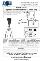
If you want switch light to dim with dash lights, refer to post #37. Dimming function is through the ground wire, so black wire from switch would connect to gray wire (-) at factory harness. Blue wire from switch would connect to green wire (+) at factory harness per attached diagram.
Always test wires with a volt meter for proper operation prior to making any connection!
Edit: Forgot to mention, these switches can only handle a 3 amp load, it is highly recommended to use a relay when interfacing with aux lighting.
If you want switch light to dim with dash lights, refer to post #37. Dimming function is through the ground wire, so black wire from switch would connect to gray wire (-) at factory harness. Blue wire from switch would connect to green wire (+) at factory harness per attached diagram.
Always test wires with a volt meter for proper operation prior to making any connection!
Edit: Forgot to mention, these switches can only handle a 3 amp load, it is highly recommended to use a relay when interfacing with aux lighting.
Attachments

Last edited:
Jhalko
New member
Here's the schematic AOB provided for wiring......
Edit: Forgot to mention, these switches can only handle a 3 amp load, it is highly recommended to use a relay when interfacing with aux lighting.
Almost all rigid wiring harness have the relay built in along with the proper fuse, they make it mostly dummy proof.
Only the super low amp dually's etc don't have the relay in the harness.
Jhalko
New member
It looks like the Rigid has a relay built in but I don't know if it drops all the way down to 3 amps.
I don't really understand what is supposed to tap into what to get the LED light bar to shut off when the headlights are shut off.
You shouldn't have to worry about amps with the relay, that takes care of the switch limits.
You'll have to wire it differently than the rigid instructions and tap into truck wiring under the hood for that. Someone that knows more than me would have to explain it, when in doubt start with Okki's build thread. But hopefully you would understand his schematics better than me.

rigtec
New member
I'll suggest this if some have reservations about tying into the head-light circuit wiring.
A good alternative to using the headlight circuit as 'a trigger' (power supply) can be the 12v Courtesy power outlet e.g., cigarette lighter, 12v accessory charger. What makes this a good choice is that the circuit shuts-off when the truck shuts off; so no chance of leaving your auxiliary lighting on when you park the truck. ...The Light Green wire is HOT, Blk/Wht wire is Gnd.
NOTICE: This Blk/Wht ground wire (mentioned above) will not provide illumination circuit dimming (Dimmer dial); that must be obtained from the 'Courtesy illumination' circuit from one of the other accessories that are on that circuit e.g., RSCA, Temp controls, wiper/side-view mirror heater, Seat heater dials... etc!
Rgds
A good alternative to using the headlight circuit as 'a trigger' (power supply) can be the 12v Courtesy power outlet e.g., cigarette lighter, 12v accessory charger. What makes this a good choice is that the circuit shuts-off when the truck shuts off; so no chance of leaving your auxiliary lighting on when you park the truck. ...The Light Green wire is HOT, Blk/Wht wire is Gnd.
NOTICE: This Blk/Wht ground wire (mentioned above) will not provide illumination circuit dimming (Dimmer dial); that must be obtained from the 'Courtesy illumination' circuit from one of the other accessories that are on that circuit e.g., RSCA, Temp controls, wiper/side-view mirror heater, Seat heater dials... etc!
Rgds
Last edited:
4Funnr
New member
Thanks for all your help so far. I think I may be getting there. Just a couple more questions.
The Rigid harness kit has three wires that attach easily to a three-pronged switch. they are labeled this way:
Black wire to gold prong (Switch ground)
Blue wire to middle prong (Switch output)
Red wire to remaining prong (Switch power)
But the AoB switch has four wires and to supply dimmable backlighting with Ignition-ON I believe it needs to be wired this way:
Black wire from AoB switch goes to Gray wire at factory harness.
Blue wire from AoB switch goes to Green wire at factory harness.
Red wire from AoB switch goes to Blue wire at Rigid harness.
Green wire from AoB switch goes to Red wire at Rigid harness.
So, what do I do withe the extra unused Black wire at the Rigid harness?
Does it not need to be used because it is the AoB switch Ground and I've already grounded the switch via the Gray wire at factory harness?
Second question is, how are you tapping into the wire from the RSCA switch? There isn't much wire to play with here. I'm a bit worried about stripping it and wiring two leads from it to reconnect it all with the new swtich.
The Rigid harness kit has three wires that attach easily to a three-pronged switch. they are labeled this way:
Black wire to gold prong (Switch ground)
Blue wire to middle prong (Switch output)
Red wire to remaining prong (Switch power)
But the AoB switch has four wires and to supply dimmable backlighting with Ignition-ON I believe it needs to be wired this way:
Black wire from AoB switch goes to Gray wire at factory harness.
Blue wire from AoB switch goes to Green wire at factory harness.
Red wire from AoB switch goes to Blue wire at Rigid harness.
Green wire from AoB switch goes to Red wire at Rigid harness.
So, what do I do withe the extra unused Black wire at the Rigid harness?
Does it not need to be used because it is the AoB switch Ground and I've already grounded the switch via the Gray wire at factory harness?
Second question is, how are you tapping into the wire from the RSCA switch? There isn't much wire to play with here. I'm a bit worried about stripping it and wiring two leads from it to reconnect it all with the new swtich.
rigtec
New member
Thanks for all your help so far. I think I may be getting there. Just a couple more questions.
The Rigid harness kit has three wires that attach easily to a three-pronged switch. they are labeled this way:
Black wire to gold prong (Switch ground)
Blue wire to middle prong (Switch output)
Red wire to remaining prong (Switch power)
Hi 4funnr,
The Ridged switch with three prongs doesn't have the capability of accommodating the courtesy lighting Dimmer feature as does the A.O.B. switch. The 'Ridged' switch has (1) 12V power in, (2) Gnd; for the on indicator light circuit, and (3) power out; to trigger the relay(s). The A.O.B. switch has the fourth pin for utilizing the courtesy light dimmer dial. Rgds!
EDIT: There shouldn't be any unused wires on the 'Ridged' harness e.g., RED 12V power input (Battery), Blk Earth Gnd (NEG Battery), and Blue, switch output power (trigger) to relay; according to your list.
Last edited:
4Funnr
New member
Hi 4funnr,
The Ridged switch with three prongs doesn't have the capability of accommodating the courtesy lighting Dimmer feature as does the A.O.B. switch. The 'Ridged' switch has (1) 12V power in, (2) Gnd; for the on indicator light circuit, and (3) power out; to trigger the relay(s). The A.O.B. switch has the fourth pin for utilizing the courtesy light dimmer dial. Rgds!
EDIT: There shouldn't be any unused wires on the 'Ridged' harness e.g., RED 12V power input (Battery), Blk Earth Gnd (NEG Battery), and Blue, switch output power (trigger) to relay; according to your list.
But if I'm tapping into the Factory ground for the dimming capability, then the Rigid ground isn't needed, right? Or should I wire them together and then in?
Similar threads


- Replies
- 13
- Views
- 3K

Members online
Total: 3,508 (members: 8, guests: 3,500)
Forum statistics
Trending content
-

-

-
-
-
Thread 'Fixed: Dead Instrument Cluster in 2003 Toyota 4Runner (Corrosion Issue)'
- TheSpeakGeek
Replies: 9