installing 2nd hho setup, need ecu help

gogetit

New member
ok guys, im brand new to this site and i need to know where the primary O2 sensor(s) wire(s) come into the ecu(s) in my wifes 2004 v6. i have been running the water4gas setup in my 2001 honda s2000 for about three months now and can honestly say that i went from 27 mpg to 40. it was a very simple system to install (two wires and a hose to the pre and post butterfly valve intake plenth. thats it. i have a couple write ups on if any of you want to go there and read them. it just pretty much goes through the process of me doing this. ive got pics showing it installed there too. im not making this up.

there is something that anyone trying this technology needs to know, that is not explained on any of the sites selling the electrolyzers. they all seem to push a map sensor adjuster, which is worthless, dont do it. what you do have to have, however, which i found out the hard way, of course, it something called an efie. this device, which is very tunable, slightly leans out the signal comming from the O2 sensors to the ecu. this is crutial, but no one really explains it on their electrolyzer sites. if you use an hho device, itll pump more O2, as well as H2 through your engine, which is the whole point. but in doing so, the O2 sensors tell the computer to dump more fuel to burn up the extra O2. what this all boils down to is that the system will work great for about a week or so and then your mileage will start to tank. this is exactly what happened to me in my s2000.

there are several versions of the efie out there but the best one ive found is the one made by.... he tells you how to make one for about 15 bucks, if you are so inclined, but im not so i bought one. several actually. there are single and dual O2 sensor setups. this pertains to the number of foreward/primary O2 sensors in the vehicle. the rear/post O2 sensors (after the cat. converters) are of no concern as this goes. also, i got the delux versions because they are in cab mounted and are very easy to just leave a volt meter hooked up to while driving to monitor the electrical offset they produce.

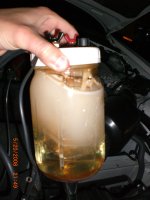
hopefully you guys believe me about all of this. im not trying to sell you anything. i really do need to know where these wires come into the ecu, and or if there is more than one ecu (i saw multiple ecu fuses under the hood). any help you can give me will very much appreciated. my car is way more simple that this 4runner. if anyone wants help/advice doing one of these setups i will be more than willing to tell you everything i know. ive already taken the electrolyzer out of my car and, just to see what happened, hooked it up to the extra vac. nipple on the post butterfly valve side of the intake manifold. there is a strong vacuum here, so keep the adjuster valve on top of the jar lid all the way tight when you start the car and them open it up two or three clicks or you could suck some water straight through the jar and into the intake. i didnt do it because i knew it could happen, but i immagine it could be very bad for someone who didnt know. after about ten seconds of running the hho through the intake, the valve ticking quieted down dramatically, which is exactly what happened to my s2000 too. the jar will eventually get hot and produce steam, which will get pulled into the engine, along with the gasses. dont put more that 1/4 tsp of baking soda or youll warp the plexi tower in the jar. this steam will clean out the carbon deposits off of your valves and other internals, helping overall efficiency.

well, now that ive talked youre eyes off, thanks for reading my post, and please help me find this O2 wire(s) answer. im an architect, not mechanic, and i really need a hand here.
 

Attachments

  • electrolyzer at night.jpg
    electrolyzer at night.jpg
    115 KB · Views: 2,956
Register to hide this ad
I wish i could help you with the info you are looking for but I can't. I am very interested, though, in what you are doing and have read quite a bit about it...waiting to see what happens and specific install info on a T4R.
 
Oxygen sensor wiring

The oxygen sensor inputs to the Engine Control Module located behind the glove compartment are a white shielded wire to pin 18 for bank 1 and a black shielded wire to pin 33 for bank 2. They are labeled OX1B and OX2B respectively in the wiring diagram but I don't know if they are labeled on the ECM. The green wire from bank 1 sensor and blue wire from bank 2 sensor also go to the ECM to pins 1 and 5 respectively. I believe these wires are for the oxygen sensor heater control that heats the sensor when the temperature of the exhaust is low. Hope this helps. I would be interested in hearing how this works on a 4Runner. Is there any drawbacks such a engine reliability due to lack of piston lubrication, converter contamination, engine knock, etc?
Let me know if I can be any further help.
Mike
 
Thx 4 posting your data gogetit! I am very excited to see the outcome of this technology. I am interested in a whole setup for my wife's 4.7 ltr. I was wondering if this system is compatible with a cold air intake? I noticed you use a glass bottle system, they have some colorful PVC canisters on ebay for sale - is there any preference as to which to buy?
 
thanks for the help mike508, this should get me going. two questions though. are the pins read top to bottom, left to right and which banks are one, two, three? i guess the real question is do you have a pic you could attach or email me? i know what signal to look for in probing for the right wires but i would rather not go through them all. those heater wires you spoke of will be what i use for the efie's power supply.

im using 87 octane in my s2000 with no knock. this is due to the more effecient burn produced by the addition of the hho. it typically runs at rpms that my wifes 4runner would see as drastic (9000 rpm redline) so im pretty sure the engine function is fine. the rpms used to pull way down in my car when i put it in neutral and then kind of struggle their way back to to 850 rpm idle but since the addition of the hho, it hasnt dont that. i dont know exactly what that means, but it seems to be running smoother. it has 50k miles on it so steam cleaning the deposits from the intake/exhaust seems to have really done it some good.

as for the glass/plexi concern. if i could get an all glass setup, i would. the more electrolyte you add the the distilled water, the more gas the system produces, but at the same time, it also produces more heat. like i said earlier, i warped my plexi tower that holds the wires in place because i used to much baking soda and it got to hot.

my s2000 has a cold air intake and has a free flow exhaust. these systems both increase mileage and power and i have seen nothing to suggest they in any way hamper the hho. in fact, my electrolyzer is plumbed directly into my cold air plenth. (i drilled a hole in the plastic and stuck the tube in the hole)
 
gogetit said:
thanks for the help mike508, this should get me going. two questions though. are the pins read top to bottom, left to right and which banks are one, two, three? i guess the real question is do you have a pic you could attach or email me? i know what signal to look for in probing for the right wires but i would rather not go through them all. those heater wires you spoke of will be what i use for the efie's power supply.

The wiring and connector files are too large to attach. Shoot me your email in a PM and I'll send them to you.

As for skeptics, I'm neutral on this. If it works then it works. Can you provide more detail on how you calculated the mpg gain (with hard numbers please like odo readings and gallons, before & after.)
 
my car does not have an on board computer that gives avg mpg, miles to empty, avg speed...all of that kind of stuff. it does, however, have a 10 gallon tank, so its pretty easy to see that if im getting 270 miles a tank ans i go to 400 miles a tank, that the difference is pretty dramatic. it did take me a few tanks to get up to that number, because the efie has to be started low and tuned upwards to find the best setting for the car. but now that im riding a steady balance between leaning the fuel and adding hho, im happy with 400 mpt.
 
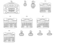
Engine Control Module Connectors

The bank 1 sensor is pin 18 on connector E4 and the bank 2 sensor is on pin 33 on connector E5. I didn't realize earlier that they were on different connectors. I'll try to send you a picture of the connectors. E4 through E8 are all Engine Control Module connectors. I don't know which is bank 1 vs bank 2. My guess would be the left exhaust would be bank 1 but it shouldn't be too hard to determine with an ohm meter. Does it really matter which is which?
Mike
 

Attachments

  • ecm connectors.jpg
    ecm connectors.jpg
    61.1 KB · Views: 2,759
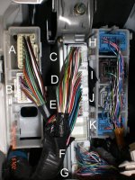
ecu image

thanks mike, i got the image but im not seeing the wire patterns. is there any way you (or anyone) can tell me a lable for this image? A=E_ and so forth? i would greatly appreciate it.
 

Attachments

  • 04 toyota 4runner ecu copy.jpg
    04 toyota 4runner ecu copy.jpg
    118.4 KB · Views: 3,033
Connector Locations

I didn't mention but my electrical wiring diagrams are for a 2006 but I don't think they have changed much. I also have 2007 and it is exactly the same connectors. Depending on your vehicle configuration there could be a lot of stuff in this area including 4WD control ECU, Tire Pressure Monitor ECU,Theft Deterrent ECU, and Transponder Key Computer as well as the Engine Control Module. My diagram shows the Engine Control Module separate from the others which is clearly not the case. All the connectors are keyed so that they can't be plugged in the wrong place. From the pictures you can see that each connector is different either in number of pins or keying (blocked areas). I would remove each connector and look at the face and compare it with the pictures until you find the correct two. My guess would be that the row of 5 connectors is the Engine Control Module since that is the correct number. Sorry I can't offer any more definitive solution.
Good luck.
Mike
 
well guys, after probing every single wire at the ecu, and not finding the signal varying between 0 and 1 volt (i did find two wires registering .3 to .6 volts) i got on the forum of the guy who makes the efies and he said that toyotas, and im asuming some other mnfrs. as well, use what are called air/fuel ratio sensors, not oxygen sensors. apparently these read a much narrower band and cannot be altered with the efie without tripping the check engine light. so to make a very long 4runner story short, this system will not work on a 4th gen 4runner. you cant just run the hho without the efie, ive tried with bad results. mike, the efie guy, did tell me that some people are having luck with the sensor spacers (ebay) but that seems a little hokey to me. ive seen other posts from this site from others trying this but i dont know when toyota made the switch between o2 sensors and a/f ratio sensors. i suppose if yours is an older model its worth a call to the dealership to see which it has. like i said at the top, my s2000 is way more simple than this 4runner. thanks for all of the help guys.
 
Sensors

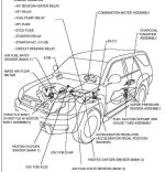
I hate to argue with your expert but according to the 2007 repair manual the oxygen sensor and air fuel ratio sensors are both included. Also I have a wiring manual for the 2006 model that shows both sensors. The air fuel ratio sensor is on connector E5 pins 22 and 30 for bank 1 and connector E5 pins 23 and 31 for bank 2. Attached is a pictorial of the location of the sensors. It looks like the O2 sensor is after the converter and the air fuel ratio sensor is before the converter.
 

Attachments

  • sensors.jpg
    sensors.jpg
    37.3 KB · Views: 3,238
Hi, I'm installing an HHO home-designed, and trying to figure out whether my 87 4Runner has a MAP or MAF sensor, but from your post I should be getting an EFIE unit??

I'd appreciate any info on whether I should worry about the MAP/MAP sensor and if so, where it is on an 87 4Runner.

If only the EFIE is needed, please let me know why too!

I looked at the page you linked to and they are charging over $100 for the EFIE, but on eBay I see similar units going for about $30. Is this the same thing?


thanks...
 
SPAM

!!! - - SPAM SPAM SPAM SPAM - - !!!

Do you notice how the original poster posted a link with a referral ID in the URL? How coincidental, that and the fact that he's supposedly achieving results that would make you want to purchase a product from the site he lists.

Expect to see more and more gas mileage scams popping up, old and new, don't buy into it unless you like throwing money away.
 
Re: SPAM

Mirlen said:
!!! - - SPAM SPAM SPAM SPAM - - !!!

Do you notice how the original poster posted a link with a referral ID in the URL? How coincidental, that and the fact that he's supposedly achieving results that would make you want to purchase a product from the site he lists.

Expect to see more and more gas mileage scams popping up, old and new, don't buy into it unless you like throwing money away.

Throwing money away? Go to YouTube and there are tons of people showing proof of the HHO gas potential and most have built the kit themselves and not selling anything. I went to IsoHunt and found the "water4gas" book that sells for $100 that explains, in detail, how to build a REAL generic HHO electrolyzer.

Go to YouTube and search for a vid called "Punch HHO Cell Debut Video" which shows them going down the road and showing "real time" data on approx. MPG on an aftermarket computer that reads MPG, ignition timing, RPM and MPH. Now, the makers of the vid do sell HHO units, nice ones, but for now, I think I'll just build my own Home Depot version until I can afford a better machined one. At freakin' $4.24 a gallon, which is what I paid tonight for 87 octane, I'll try anything to get my MPG's down aside from driving habits.
 
:confused:I am going to assume for a split second HHO would work. Isn't one of the best sources for hydrogen an overcharged lead-acid battery? Why all this monkey business? Wouldn't the easiest thing to do be take two golf-cart batteries, wire a cumulative of 5 cells to the alternator and recover the gas? Top it off with distilled water every 3-5 days and you would have hydrogen, right?

It's been so long since school but I seem to remember hydrogen is a by-product of charging batteries hence the explosion warning labels on batteries.

If HHO was the answer we
 
Last edited:
I couldn't have said it better. I think it was Consumer Report that had an evaluation of these devices and found that they did not increase MPG. So, with a fair and thorough evaluation, you may get a damaged engine with no offsetting benefit. If there was a real benefit you are naive to think that the implementation would be a shade tree operation.
 
Re: Re: SPAM

tfxpzeke01 said:
Throwing money away? Go to YouTube and there are tons of people showing proof of the HHO gas potential

There are also a bunch of videos of people unlocking cars over their cell phones, do ya believe those too? *chuckle*
 

Members online

No members online now.

Forum statistics

Threads
278,309
Messages
3,554,068
Members
248,016
Latest member
Advally Service

Trending content

Back
Top