
You are using an out of date browser. It may not display this or other websites correctly.
You should upgrade or use an alternative browser.
You should upgrade or use an alternative browser.
One cause & fix for "VSC TRAC" & "VSC OFF" lights, Zero Point Calibration
- Thread starter MicaBlue03
- Start date
Vrsc trac, vrsc off question
I,ve just come from having a new key calibrated for my 2004 Toyota 4runner v8, and when I picked it up, the Vrsc trac, and vrsc off lights were on. The Service guy said ther was no way that making a new key could have caused that. If I'm reading the posts correctly, could they have altered the computer and caused the problem? Thanks. masteral
I,ve just come from having a new key calibrated for my 2004 Toyota 4runner v8, and when I picked it up, the Vrsc trac, and vrsc off lights were on. The Service guy said ther was no way that making a new key could have caused that. If I'm reading the posts correctly, could they have altered the computer and caused the problem? Thanks. masteral
20034RunnerSR5
New member
I appreciate this thread and the info. I am not very good with this stuff, however. I have read the OP over and over and still have no clue how to do this it what to do. I wanted to try it but don't even know where to begin. Would anyone be willing to explain this laymans terms?
Code readers of several types are getting cheaper, and I think it's a good idea to have one if you're going to do much of your own work or if you hope to learn more to protect yourself from incompetent or dishonest service departments. If you've read the code yourself you can sometimes stop the service folks from selling you a load of something you don't need. Also, the code readers can often be used to reset the check engine light to see if the problem was a isolated event.
Thanks for the great post. I would like to get one of those code readers so I can make sure my issue is not an isolated incident. Do you know where I can locate one for purchase? Any suggested brands or types?
I appreciate any assistance you could provide.

Ezspike
New member
Does anyone have any other ideas?.. Lights are still on and no ABS or VSC working. Damnit..we have snow!
I don't discount anything that has been posted on this string but what worked for me as told on another page in this form was to make sure my gas cap was tight and then disconnect the battery for 10 minutes are so and reconnect the battery.... lights went off and that was 30k ago...cant tell you why but it worked for me.
Ez
jackharvey8
New member
I have a 2004 4runner with 180k miles - my VSC TRAC, VSC off, ABS and BRAKE lights come on intermittently. Also, my speedometer has started to stop working intermittently also (when speedometer stops - so does cruise control).
I took it to the dealer and there were no codes recorded for anything - the fuses were all ok. any ideas what could be going on?
I took it to the dealer and there were no codes recorded for anything - the fuses were all ok. any ideas what could be going on?


20034RunnerV84x2
New member
So after talking with my buddies back at the shop, we tried the ZPC & nada. Still have the lights on, etc. The code coming up for it is C1234 - pretty much saying either the YRS is faulty, or there is a problem in the wiring. Honestly hoping for the wiring idea because it can be very easily fixed with a bit of soder and shrink wrap, and looking around the YRS new is over $800 and I CAN NOT pay that being 18 and headed to college. For ****s sake, I can't even afford a set of used tires and mine could blow at any time now (Sucks going into college, huh?) as well as a TB/WP. So if you have an extra one and want to let it go after I finish getting this diagnosing done for like $20 + shipping I'll love you forever 
Can't stand this. It also WILL NOT accept a ZPC - do I need them to use an older scanner or something? PLEASE HELP! These lights are about to drive me insane and they've been on for about a year now.
Can't stand this. It also WILL NOT accept a ZPC - do I need them to use an older scanner or something? PLEASE HELP! These lights are about to drive me insane and they've been on for about a year now.
Something else to check is the wheel speed sensor harness I just changed my cv axel and must of stretched it or something abs vsc trac and vsc came on in my 2004. Purchased one from the stealership for 70 bucks easy to install took a couple turn on turn offs but everythings good now.
20034RunnerV84x2
Seems like thats your problem^^.I know alot of scan tools wont work I wasnt getting codes from the one at autozone it didnt even have an abs option . I forgot exsactly what code I got but it was wheel speed sensor and abs off a snap on chrome series im suprised noone else had the same problem as me the zpc didnt work for me at all but for those who cant figure out how to do it there is a youtube video for the 2004
Seems like thats your problem^^.I know alot of scan tools wont work I wasnt getting codes from the one at autozone it didnt even have an abs option . I forgot exsactly what code I got but it was wheel speed sensor and abs off a snap on chrome series im suprised noone else had the same problem as me the zpc didnt work for me at all but for those who cant figure out how to do it there is a youtube video for the 2004
robwilliams50
New member
Zero Point Calibration - after emissions test Ontario
Just wanted to thanks all the post on this thread. After getting the Ontario Drive Clean Emissions test at the Downtown Toyota dealership in Toronto both the VSC Trac VSC OFF lights were on. Took back to the dealership as i stated they were the ones that caused these lights to go on. Mentioned to them that i needed to get a Zero Point Calibration. Well i'm not sure there software is messed up but they proceeded to tell me my battery was low voltage and that i needed a new battery before they could do the calibration. I then watched them run the calibration again (well i think it was the test as was not able to see fully) and again couldn't reset the light and told me sorry nothing we could do its your problem. Knowing my battery was only 8 months old i knew they were trying to rip me off. I then followed the instructions from the service bulletin posted on this thread and using two paper clips i was able to perform the calibration.
Watch out for shady dealerships trying to get your money to fix this issue when the emissions test they ran in the first place caused the issue. Such an easy fix!
Just wanted to thanks all the post on this thread. After getting the Ontario Drive Clean Emissions test at the Downtown Toyota dealership in Toronto both the VSC Trac VSC OFF lights were on. Took back to the dealership as i stated they were the ones that caused these lights to go on. Mentioned to them that i needed to get a Zero Point Calibration. Well i'm not sure there software is messed up but they proceeded to tell me my battery was low voltage and that i needed a new battery before they could do the calibration. I then watched them run the calibration again (well i think it was the test as was not able to see fully) and again couldn't reset the light and told me sorry nothing we could do its your problem. Knowing my battery was only 8 months old i knew they were trying to rip me off. I then followed the instructions from the service bulletin posted on this thread and using two paper clips i was able to perform the calibration.
Watch out for shady dealerships trying to get your money to fix this issue when the emissions test they ran in the first place caused the issue. Such an easy fix!
it works!
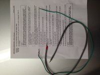
Love this forum.... Last Saturday I sent my wife to local oil change shop to have annual inspection done on my 04 4Runner. She returned with VSC TRAC and VSC OFF warning lights. After some deep breaths and calming myself down, I tried to let common sense take over. Surely this was caused by inspection process. After finding this thread, it seemed like the logical root cause, particularly since I know the inspection involves the testing facility plugging into the OBDII connector to check for stored trouble codes. I fabricated a couple of jumper wires and followed the procedure. Worked like a champ! Total time - 30 mins from start to finish. Pic of wires attached. I used "U" blade crimp connectors on end of some scrap wire I found in my electrical stuff. I cut off one side of the "U". They fit perfectly in the OBDII connector and held. Another successful fix. Did I mention I love this forum?
Love this forum.... Last Saturday I sent my wife to local oil change shop to have annual inspection done on my 04 4Runner. She returned with VSC TRAC and VSC OFF warning lights. After some deep breaths and calming myself down, I tried to let common sense take over. Surely this was caused by inspection process. After finding this thread, it seemed like the logical root cause, particularly since I know the inspection involves the testing facility plugging into the OBDII connector to check for stored trouble codes. I fabricated a couple of jumper wires and followed the procedure. Worked like a champ! Total time - 30 mins from start to finish. Pic of wires attached. I used "U" blade crimp connectors on end of some scrap wire I found in my electrical stuff. I cut off one side of the "U". They fit perfectly in the OBDII connector and held. Another successful fix. Did I mention I love this forum?
Attachments
If you never got your lights fixed and your symptoms are exactly like the original post describes, I'll tell you that the instructions on page 7 of the PDF file actually work.
1. Ensure the shift lever is in
“P” range.
2. Turn the ignition switch ON.
3. Using SST 09843–18040, repeat a
cycle of short and open between
terminals Ts and CG of DLC3 4 times
or more within 8 seconds. Verify that
the VSC indicator light is lit indicating
the recorded zero point is erased.
4. Turn the ignition switch OFF.
5. Be sure the terminals Ts and CG of
DLC3 are disconnected.
6. Turn the ignition switch ON.
7. Check that the VSC warning light
goes off about 15 seconds after the
ignition switch is turned ON.
8. After ensuring that the VSC warning
light remains OFF for 2 seconds, turn
the ignition switch OFF.
9. Connect the terminal Ts and CG of
DLC3 using SST 09843–18040.
10.Turn the ignition switch ON.
11. After turning the ignition switch ON,
check that the VSC warning light
is lit for about 4 seconds and then
starts quick blinking at
0.13 second intervals.
Ts
CG
What you need to know to make it easier to understand is that wherever it talks about the "SST 09843–18040" you can simply use speaker wire. (Actually, any two wires will do, but speaker wire seamed to make sense since they're already attached for simplicity) Take about 2 feet of speaker wire and strip about 1/2" of the sheath off the ends. Since speaker wires have two wires attached together you then split them apart so that there is enough slack to be able to insert them into the pin holes on the dock for the OBDII sensor under the left hand side of the driver side foot compartment (near your left shin).
When you look at the diagram in the PDF file it shows you the two pin holes in the dock that you will need to use. They are #14 and #4. Take one end of the speaker wire length that you have split apart and pulled the sheath off using wire strippers. I used a 14 gauge wire and needed to peal about 1/3 of the amount of wire strands away before twisting the rest of the wires together (so either a 16 or 18 gauge wire would probably work better). This made the thickness of the twisted end the right size to plug into pin holes 14 and 4 on the harness. Once you get them inserted into the harness try to be gentle so that you do not pull them out by accident as you are going through the rest of the steps.
Follow the rest of the steps in the instructions. When it tells you in step 3 to "short and open" multiple times, all you are doing is touching the other end of the two wires together and separating them multiple times within the 8 seconds.
In step 9 where it says to connect the terminals, all you need to do is twist the two wires on the other end together, completing the circuit between the #4 and #14 pins.
I hope this makes sense for you. I tried to upload a picture of the wires that I used, but this computer is giving me fits for some reason, so I'm not able to right now. If it turns out that you need more information, let me know and I'll download the pics off my phone that I took onto another computer and send them to you.
Good luck. Honestly, it took me longer to strip the wires from the speaker wire than it did to actually run through the whole diagnostic routine once it was set up.
1. Ensure the shift lever is in
“P” range.
2. Turn the ignition switch ON.
3. Using SST 09843–18040, repeat a
cycle of short and open between
terminals Ts and CG of DLC3 4 times
or more within 8 seconds. Verify that
the VSC indicator light is lit indicating
the recorded zero point is erased.
4. Turn the ignition switch OFF.
5. Be sure the terminals Ts and CG of
DLC3 are disconnected.
6. Turn the ignition switch ON.
7. Check that the VSC warning light
goes off about 15 seconds after the
ignition switch is turned ON.
8. After ensuring that the VSC warning
light remains OFF for 2 seconds, turn
the ignition switch OFF.
9. Connect the terminal Ts and CG of
DLC3 using SST 09843–18040.
10.Turn the ignition switch ON.
11. After turning the ignition switch ON,
check that the VSC warning light
is lit for about 4 seconds and then
starts quick blinking at
0.13 second intervals.
Ts
CG
What you need to know to make it easier to understand is that wherever it talks about the "SST 09843–18040" you can simply use speaker wire. (Actually, any two wires will do, but speaker wire seamed to make sense since they're already attached for simplicity) Take about 2 feet of speaker wire and strip about 1/2" of the sheath off the ends. Since speaker wires have two wires attached together you then split them apart so that there is enough slack to be able to insert them into the pin holes on the dock for the OBDII sensor under the left hand side of the driver side foot compartment (near your left shin).
When you look at the diagram in the PDF file it shows you the two pin holes in the dock that you will need to use. They are #14 and #4. Take one end of the speaker wire length that you have split apart and pulled the sheath off using wire strippers. I used a 14 gauge wire and needed to peal about 1/3 of the amount of wire strands away before twisting the rest of the wires together (so either a 16 or 18 gauge wire would probably work better). This made the thickness of the twisted end the right size to plug into pin holes 14 and 4 on the harness. Once you get them inserted into the harness try to be gentle so that you do not pull them out by accident as you are going through the rest of the steps.
Follow the rest of the steps in the instructions. When it tells you in step 3 to "short and open" multiple times, all you are doing is touching the other end of the two wires together and separating them multiple times within the 8 seconds.
In step 9 where it says to connect the terminals, all you need to do is twist the two wires on the other end together, completing the circuit between the #4 and #14 pins.
I hope this makes sense for you. I tried to upload a picture of the wires that I used, but this computer is giving me fits for some reason, so I'm not able to right now. If it turns out that you need more information, let me know and I'll download the pics off my phone that I took onto another computer and send them to you.
Good luck. Honestly, it took me longer to strip the wires from the speaker wire than it did to actually run through the whole diagnostic routine once it was set up.
It's totally do-able.
If you never got your lights fixed and your symptoms are exactly like the original post describes, I'll tell you that the instructions on page 7 of the PDF file actually work.
1. Ensure the shift lever is in
“P” range.
2. Turn the ignition switch ON.
3. Using SST 09843–18040, repeat a
cycle of short and open between
terminals Ts and CG of DLC3 4 times
or more within 8 seconds. Verify that
the VSC indicator light is lit indicating
the recorded zero point is erased.
4. Turn the ignition switch OFF.
5. Be sure the terminals Ts and CG of
DLC3 are disconnected.
6. Turn the ignition switch ON.
7. Check that the VSC warning light
goes off about 15 seconds after the
ignition switch is turned ON.
8. After ensuring that the VSC warning
light remains OFF for 2 seconds, turn
the ignition switch OFF.
9. Connect the terminal Ts and CG of
DLC3 using SST 09843–18040.
10.Turn the ignition switch ON.
11. After turning the ignition switch ON,
check that the VSC warning light
is lit for about 4 seconds and then
starts quick blinking at
0.13 second intervals.
Ts
CG
What you need to know to make it easier to understand is that wherever it talks about the "SST 09843–18040" you can simply use speaker wire. (Actually, any two wires will do, but speaker wire seamed to make sense since they're already attached for simplicity) Take about 2 feet of speaker wire and strip about 1/2" of the sheath off the ends. Since speaker wires have two wires attached together you then split them apart so that there is enough slack to be able to insert them into the pin holes on the dock for the OBDII sensor under the left hand side of the driver side foot compartment (near your left shin).
When you look at the diagram in the PDF file it shows you the two pin holes in the dock that you will need to use. They are #14 and #4. Take one end of the speaker wire length that you have split apart and pulled the sheath off using wire strippers. I used a 14 gauge wire and needed to peal about 1/3 of the amount of wire strands away before twisting the rest of the wires together (so either a 16 or 18 gauge wire would probably work better). This made the thickness of the twisted end the right size to plug into pin holes 14 and 4 on the harness. Once you get them inserted into the harness try to be gentle so that you do not pull them out by accident as you are going through the rest of the steps.
Follow the rest of the steps in the instructions. When it tells you in step 3 to "short and open" multiple times, all you are doing is touching the other end of the two wires together and separating them multiple times within the 8 seconds.
In step 9 where it says to connect the terminals, all you need to do is twist the two wires on the other end together, completing the circuit between the #4 and #14 pins.
I hope this makes sense for you. I tried to upload a picture of the wires that I used, but this computer is giving me fits for some reason, so I'm not able to right now. If it turns out that you need more information, let me know and I'll download the pics off my phone that I took onto another computer and send them to you.
Good luck. Honestly, it took me longer to strip the wires from the speaker wire than it did to actually run through the whole diagnostic routine once it was set up.
If you never got your lights fixed and your symptoms are exactly like the original post describes, I'll tell you that the instructions on page 7 of the PDF file actually work.
1. Ensure the shift lever is in
“P” range.
2. Turn the ignition switch ON.
3. Using SST 09843–18040, repeat a
cycle of short and open between
terminals Ts and CG of DLC3 4 times
or more within 8 seconds. Verify that
the VSC indicator light is lit indicating
the recorded zero point is erased.
4. Turn the ignition switch OFF.
5. Be sure the terminals Ts and CG of
DLC3 are disconnected.
6. Turn the ignition switch ON.
7. Check that the VSC warning light
goes off about 15 seconds after the
ignition switch is turned ON.
8. After ensuring that the VSC warning
light remains OFF for 2 seconds, turn
the ignition switch OFF.
9. Connect the terminal Ts and CG of
DLC3 using SST 09843–18040.
10.Turn the ignition switch ON.
11. After turning the ignition switch ON,
check that the VSC warning light
is lit for about 4 seconds and then
starts quick blinking at
0.13 second intervals.
Ts
CG
What you need to know to make it easier to understand is that wherever it talks about the "SST 09843–18040" you can simply use speaker wire. (Actually, any two wires will do, but speaker wire seamed to make sense since they're already attached for simplicity) Take about 2 feet of speaker wire and strip about 1/2" of the sheath off the ends. Since speaker wires have two wires attached together you then split them apart so that there is enough slack to be able to insert them into the pin holes on the dock for the OBDII sensor under the left hand side of the driver side foot compartment (near your left shin).
When you look at the diagram in the PDF file it shows you the two pin holes in the dock that you will need to use. They are #14 and #4. Take one end of the speaker wire length that you have split apart and pulled the sheath off using wire strippers. I used a 14 gauge wire and needed to peal about 1/3 of the amount of wire strands away before twisting the rest of the wires together (so either a 16 or 18 gauge wire would probably work better). This made the thickness of the twisted end the right size to plug into pin holes 14 and 4 on the harness. Once you get them inserted into the harness try to be gentle so that you do not pull them out by accident as you are going through the rest of the steps.
Follow the rest of the steps in the instructions. When it tells you in step 3 to "short and open" multiple times, all you are doing is touching the other end of the two wires together and separating them multiple times within the 8 seconds.
In step 9 where it says to connect the terminals, all you need to do is twist the two wires on the other end together, completing the circuit between the #4 and #14 pins.
I hope this makes sense for you. I tried to upload a picture of the wires that I used, but this computer is giving me fits for some reason, so I'm not able to right now. If it turns out that you need more information, let me know and I'll download the pics off my phone that I took onto another computer and send them to you.
Good luck. Honestly, it took me longer to strip the wires from the speaker wire than it did to actually run through the whole diagnostic routine once it was set up.
Thank You!
Thanks MicaBlue03 for the information. Your symptoms were exactly the same as I was experiencing. I used speaker wires to make the connection between the #4 and #14 pins and it worked like a champ! I was initially perplexed by the lights coming on, but the OBDII sensor issue made complete sense since I had someone hook one up just prior to the VSC and VSC TRK lights coming on. The information you all provided made this a simple remedy, and something that anybody with spare speaker wire capable of doing. Thanks again!
Thanks MicaBlue03 for the information. Your symptoms were exactly the same as I was experiencing. I used speaker wires to make the connection between the #4 and #14 pins and it worked like a champ! I was initially perplexed by the lights coming on, but the OBDII sensor issue made complete sense since I had someone hook one up just prior to the VSC and VSC TRK lights coming on. The information you all provided made this a simple remedy, and something that anybody with spare speaker wire capable of doing. Thanks again!

jcruiser70
New member
To clarify, is the wire left in place completing the circuit or removed?
I've tried this a couple times and the lights stay off for a few hundred feet, then come back on.
I was getting the code for the upstream drivers side cat, but after doing some reading here, found that it could be the o2 sensor, bought a Denso off Amazon and the cel has been off for almost a week now!!
Now if I could just get the vsc lights off I'd be a happy camper!
I've tried this a couple times and the lights stay off for a few hundred feet, then come back on.
I was getting the code for the upstream drivers side cat, but after doing some reading here, found that it could be the o2 sensor, bought a Denso off Amazon and the cel has been off for almost a week now!!
Now if I could just get the vsc lights off I'd be a happy camper!
First of all...thank you Micablue & all thread participants!
My symptoms began after 4 tires were replaced & the TPS were rebuilt.
SYMPTOMS - all these lights would only come on intermittently. The code reader did not indicate a code....read by O'Reilly"s
After reading this & many other threads I tried the 'Zero Point Calibration", but I could not get past #7. C warning light would not go off.
I then made a list of other possible causes:
#1 ABS sensor wire continuity
#2 Weak battery
#3 ABS Fuse
#4 Low brake fluid .... See Toyota Service Manual low brake fluid link below
#5 Tire pressure
#6 Brake light switch operation
#7 Master cylinder electrical connections Two connectors
I then performed the "Zero Point Calibration" one more time...but only to step #7, checked #'s 1, 2, 3, 5, , 7. For # 7 I disconnected & reconnected both connectors.
I then added brake fluid....the level was down slightly.....original brakes w/66,000 miles.
I am now two weeks & probably 20 start/stops w/o the lights returning.
Hopefully, this will help others who had the same symptoms as me.
My symptoms began after 4 tires were replaced & the TPS were rebuilt.
SYMPTOMS - all these lights would only come on intermittently. The code reader did not indicate a code....read by O'Reilly"s
After reading this & many other threads I tried the 'Zero Point Calibration", but I could not get past #7. C warning light would not go off.
I then made a list of other possible causes:
#1 ABS sensor wire continuity
#2 Weak battery
#3 ABS Fuse
#4 Low brake fluid .... See Toyota Service Manual low brake fluid link below
#5 Tire pressure
#6 Brake light switch operation
#7 Master cylinder electrical connections Two connectors
I then performed the "Zero Point Calibration" one more time...but only to step #7, checked #'s 1, 2, 3, 5, , 7. For # 7 I disconnected & reconnected both connectors.
I then added brake fluid....the level was down slightly.....original brakes w/66,000 miles.
I am now two weeks & probably 20 start/stops w/o the lights returning.
Hopefully, this will help others who had the same symptoms as me.
Attachments
Last edited:
I had a separate post about this before I saw this one, so I figured I would let you know what I did that led to the lights coming on.
I have a 04 SR5 V6. I cleaned the MAF, Throttle Bottle, took out the hydrocarbon filter (thanks to a mod sticky on here) and cleaned and reoiled my K&N filter (although from reading on here it sounds like I should buy a different one). After this, i put the negative back on the battery, and these lights showed up, along with the stereo not working. I checked all the fuses and wiring (what I could) and couldn't figure it out. I disconnected the negative again, and when I connected it again, the radio then worked, but BOTH VSC lights were still on (NOT the CEL light). I did the ZPC, and it worked like a charm. Followed the directions exactly as posted in the second or third post on here, directly from Toyota.
I have a 04 SR5 V6. I cleaned the MAF, Throttle Bottle, took out the hydrocarbon filter (thanks to a mod sticky on here) and cleaned and reoiled my K&N filter (although from reading on here it sounds like I should buy a different one). After this, i put the negative back on the battery, and these lights showed up, along with the stereo not working. I checked all the fuses and wiring (what I could) and couldn't figure it out. I disconnected the negative again, and when I connected it again, the radio then worked, but BOTH VSC lights were still on (NOT the CEL light). I did the ZPC, and it worked like a charm. Followed the directions exactly as posted in the second or third post on here, directly from Toyota.
PewaukeeDave
New member
VSC Trac & VSC OFF lights
Thanks for the great fix MicaBlue03!!! It worked the first time and saved me a few bucks I'm sure!!!
Thanks for the great fix MicaBlue03!!! It worked the first time and saved me a few bucks I'm sure!!!
Similar threads
- Replies
- 1
- Views
- 926

- Replies
- 1
- Views
- 35K

- Replies
- 2
- Views
- 3K


