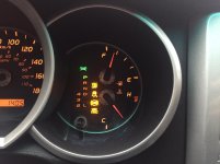
T4R-2002 Zero Pt. Calibration Question: Which Pins for Ts and CG?
Hi guys:
This is my 1st post here. I drove many Volvo wagons from 1986 to now and loved them but now I just got a 2002 4Runner SR5 with 171K miles and love it!!!
This is a GREAT forum; your posts are excellent.
My 4Runner 2002 failed "Overall Emissions" inspection: Heated Catalytic Converters/Secondary Air Injection/ A/C Refrigerant/EGR Systems - Unsupported; Catalytic Converters/Evaporative System - Not Ready.
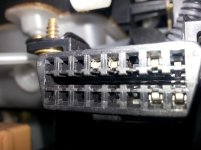
I tried unsuccessfully the below Zero Pt. Calibration method but I am unsure if DLC3 pin #s 4 and 14 are also the SAME for the 4Runner 2002. I attach an image of my truck's DLC3. It appears I have pin # 4 but not pin # 14. Am I correct? Maybe, I must use different pin #s for this task. Please advise, if you know.
In any event, I returned my truck to the dealer for service so it would pass inspection.
Some general comments:
1. Cylinder valve cover leaks - have strong smell whenever I turn heat ON. I will purchase ALL required parts per other posts and will replace failing parts.
2. Truck steers right and its steering wheel vibrates a little at 70+ mph: I replaced already the 2 sway bar bushings but no change. Next, I will replace both front ball/roll joint links (4 parts). If still no fix, then I will replace the front lower control arm bushings. Tires are balanced. I will check the rotors' uniformity and any U-joints for defects, if the vibration issue continues after my above replacements.
3. I have no data when the previous PO replaced the timing belt. So, I will open its cover and try to qualitatively determine is remaining life, if any

! I have bought all parts (all belts, water pump, thermostat, gaskets, etc.) and will do the job. Absent that, I can ruin this truck.
4. This truck has P265/70R16 tires. Should I expect better miles/gal performance vs the P225/75R15 tires? I think so.
5. Power-flushed the transmission/power steering fluids with the engine running and just key in the ON position, respectively, and w/o external tools. I believe that is the proper way.
6. Plan to install an external transmission cooler and filter to eliminate the possibility of destroying my transmission - milky problem.
7. I will install the controlled gap E3.48 type of spark plugs, thereby eliminating variable ignition/spark of the gas/air mixture and improving performance.
8. Underbody of truck is heavily corroded, especially from around the rear axle and towards the back of it: I removed as much rust as I could, then spray-painted 3X with a black rust-prevention paint and then 3x rubber-coated that area. Now, it looks great and it should last quite a while.
******************************************************************************
Zero Point Calibration of Yaw Rate and Deceleration Sensors Using SST 09843–18040 or Two (2) - 24” Wires with 3/8” Length Paperclips.
When having replaced the yaw rate sensor, deceleration sensor or the ECU, perform the process for zero point of yaw rate and deceleration sensors as shown below.
NOTE:
While performing the zero point procedure, do not tilt, move or shake the vehicle. The vehicle must remain in a stationary condition throughout the entire process. Do not start the engine and be sure to perform the procedure on a level surface with an inclination of less than 1%.
1. Ensure the shift lever is in “P” range.
2. Turn the ignition switch ON.
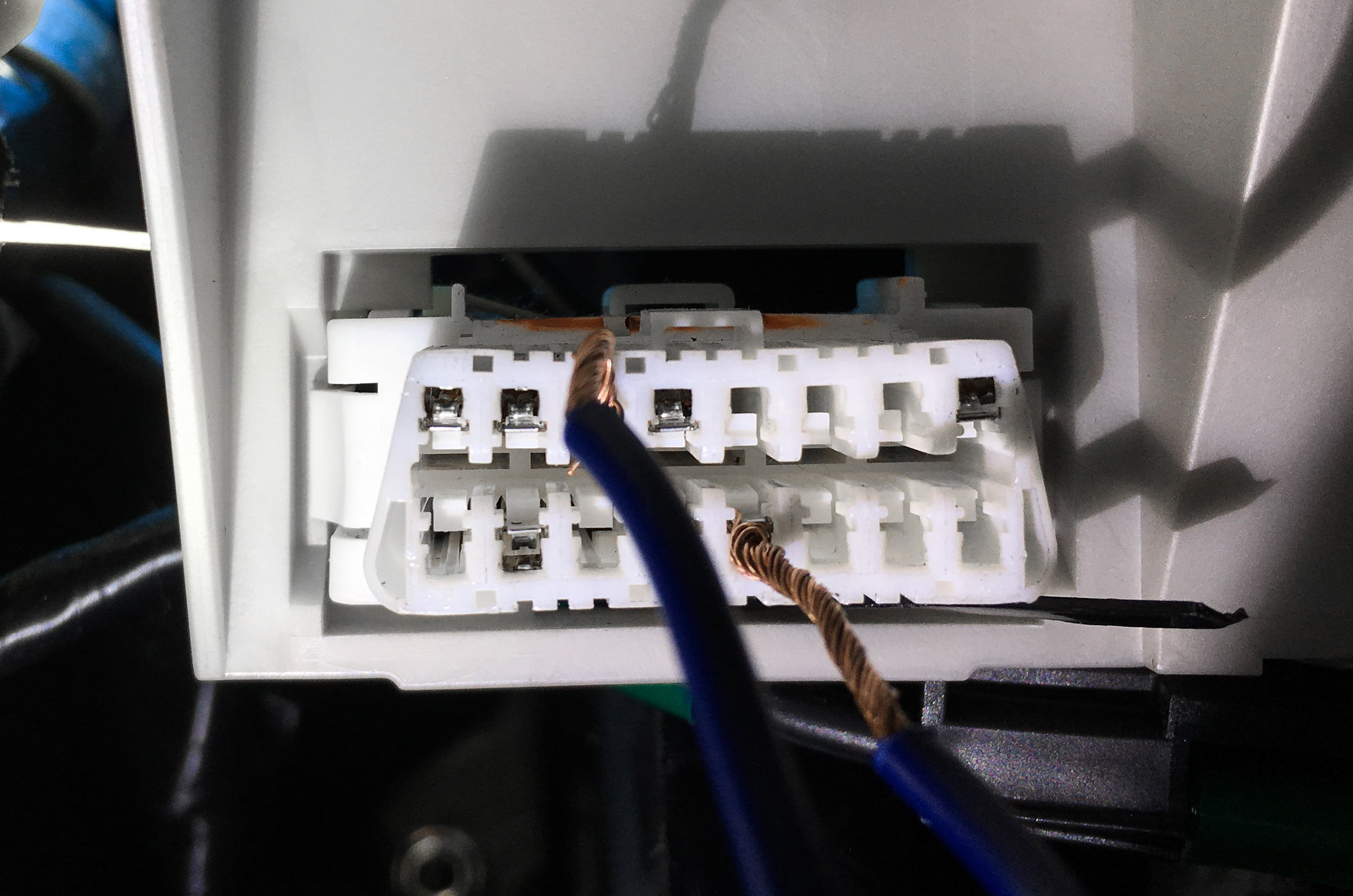
3. Take 2 pieces of insulated wire about 24" long each and taped them alongside each other, and stripped both ends. I soldered a 3/8" length of a heavy paper clip to one end of each of the wires and electrically taped them to prevent shorting to make the wire fit securely in the female terminals of the OBDII connector.
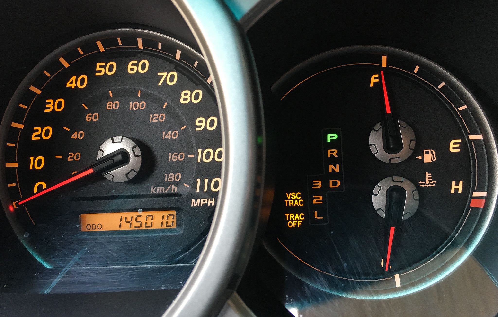
Repeat a cycle of short and open between terminals Ts = # 14 and CG = # 4 sockets of DLC3 4 times or more within 8 seconds using SST 09843–18040 or the above 2 wires. Verify that the VSC indicator light is lit indicating the recorded zero point is erased.
4. Turn the ignition switch OFF.
5. Be sure the terminals Ts = # 14 and CG = # 4 of DLC3 are disconnected.
6. Turn the ignition switch ON.
7. Check that the VSC warning light goes off about 15 seconds after the ignition switch is turned ON.
8. After ensuring that the VSC warning light remains OFF for 2 seconds, turn the ignition switch OFF.
9. Connect the terminal Ts and CG of DLC3 using SST 09843–18040.
10. Turn the ignition switch ON.
11. After turning the ignition switch ON, check that the VSC warning light is lit for about 4 seconds and then starts quick blinking at 0.13 second intervals.
12. After ensuring the blinking of the VSC warning light for 2 seconds, turn the ignition switch OFF.
13. Remove the SST from terminals Ts and CG of DLC3. Drive the vehicle to confirm there are no re–occurring lights or DTCs.







 out:
out: