SOLUTION: 4th gen Personal (aka Map) Light mod

greasefingers said:
I was thinking about doing this Mod soon. After thinking about the ILE circuit, I think I will install two diodes, one each prior to each SPDT switch. This way it would insure that electricity would only flow from the ILE to the Map light switches and never the other way around. But I need to stare at the entire circuit diagram first. Does this make sense to anyone else?

ILE is on the ground path and is thus a current sink, not a supply. This mod uses ILE exactly the same way as it's used on the other interior lighting circuits. It's not the case that it joins the ILE circuit to another (potentially active) power circuit.
 
ScottAW said:
Rando - Are you saying I can tap into the ILE ribbon cable right near the fuse panel?


Yes, it terminates at one of the connectors on the front of the fuse panel.
 
greasefingers said:
The first thing that comes to my mind when using a trigger, like the Body ILE circuit, is to protect that circuit. I am not positive, but that is not simply a 12volt supply.
You're thinking is spot on correct. Safety should be your #1 thought before you do any mod. The ILE circuit works by completing the ground path to the various interior lights. All this mod does is add ILE to the ground path of the map lights by using a (previously) unused switch position.

This is the OEM wiring for the Map lights. As you can see, just basic on/off functionality. The dome relay switches the lights off if you leave them on.
Battery==Dome relay==Map Light Switch Pole
GND==============Map Light Switch Pos1 (On)
N/C ==============Map Light Switch Pos2 (Off)


This is the OEM wiring for other overhead lights. These are the same as above except when in the DOOR position. In that case, the ground path is controlled by ILE via the Body ECU. This does the fade out effect. If you leave them in the ON position, the dome relay switches them off.
Battery==Dome relay==Overhead Light Switch Pole
GND==============Overhead Light Switch Pos1 (On)
N/C ==============Overhead Light Switch Pos2 (Off)
GND==Body ECU(ILE)==Overhead Light Switch Pos3 (Door)


This is the wiring for the mod'd Map lights. As you can see, your map lights now work like above with the OFF position having been turned into the new DOOR position.
Battery==Dome relay==Map Light Switch Pole
GND==============Map Light Switch Pos1 (On)
GND==Body ECU(ILE)==Map Light Switch Pos2 (Door)


I'm not sure how a diode will help here. It is true that this mod puts your ILE circuit at risk. When all the lights are on, your ILE circuit will be sinking more current than in the OEM design. I have no idea if it can actually tolerate this -- but it's been working fine for me.

If Toyota did their job right, it should be OK since ILE should be able to handle a short circuit that might happen when changing bulbs. The fuse that protects the dome light circuit should blow before the ILE circuit is damaged ... at least that's how I would have built it.
 
Last edited:
rando:
Thank you for replying to my post. I did not reply right away because I could not find my FSM for Electrical Wiring Diagrams, and this was killin me. Finally, for the first time ever, I took a long stare at it. I started with page one because I am not familiar with Toyota. It took awhile to get used to the White wires w/black stripes being “grounds” and then agian then are sometimes Brown. Also, the gray shaded areas in the manual are junction blocks. Anyway, examining the Interior lighting section and also remembering what you stated in your post; it all now makes sense to me. Before this I assumed that the ILE wire was the supply. Thanks for clearing that up. If I had no resources, I would have installed a diode using my twisted logic. I am sure, from my original assumptions, that I would also installed the diode backwards. And then what would I have thought then the lights do not work. Since the Map Light is represented as only a Blue Box, on the schematic, how on earth did you know that there would be an additional THIRD terminal on it? You deserve a lot of credit for carefully thinking about this Mod
 
I didn't know ... just hoped. Since I had the spare map light unit laying around (left over from adding the Homelink unit), all I had to do was look.
 
Finally did this mod tonight, probably took about 30-45 minutes all said and done. I had to take a break inbetween for supper, but it is a pretty easy mod to do. I thought I'd take pictures of the process, maybe it will help out those who decide to do it in the future.

Here's a picture of the hole where you pull the console out, nothing too exciting really. Just pull down on the front edge, fairly hard, as there are two spring retaining clips & plastic velcro to unattach.

DSCN2602.JPG


Didn't take long at all to actually modify the console. I routed my wires a little differently than Rando, doesn't matter though as there is lots of room to work with here.

DSCN2601.JPG


A close up where you can see how I attached the wires so they don't move. I just used a hot super glue gun, works really well for this application.

DSCN2600.JPG


And here is a close up shot of the back of the switch, where you can see that two of the terminal plug-in ports have the stock spade terminals sticking inside them, and the third has the 18 gauge stranded wire. A tip - cut a 1/4" of the insulation off, don't wind up the stranded wire. It won't fit in the tight slot. Instead, just leave it as is and work it into the slot carefully. It's easy, trust me!

DSCN2598.JPG


And the driver's side A-pillar is revealed. You can see the umbillical cord of wires, along with two red & black wires. The latter power the autodimmming mirror that I picked up from Rando. :D

DSCN2603.JPG


The white w/ blue dashes ribbon cable is show here. I used my knife and split the 3 wires within the ribbon apart to make room for the splice connector. Pretty elementary, just tap into the center wire and you're almost done. I wrapped mine with electrical tape, just to be safe.

DSCN2604.JPG


I ran the wire just above the head liner's edge, it tucks in there really easy. Connect the two tires from the console to the lead wire and you are done. I used a wire nut with electrical tape, didn't have any connectors on hand. A tip: Close your door so the ILE circuit isn't powering the overhead lights. This way, when you make the connection you don't have to worry about shorting the line out or anything. Better safe than sorry IMO.

DSCN2606.JPG


Put it all together again and you are done. Piece of cake. Thanks Rando!!!!

DSCN2607.JPG
 
Nice write up! I've got to learn how to make my camera work like that! Your glue job is excellent!

There's just a couple of things I want to add.

1) Head to Home Depot and get some spade connectors. The wire nuts are not really designed for a high vibration environment like a car.

2) ALWAYS disconnect your battery before working on you car's electrical system.

PS: I'm glad to see the mirror worked out for you too.

BTW, are you sure you have the curtain airbags? I kind of expected to see the tips of the squibs in the A-pillar.
 
Last edited:
Nope, I don't have airbags there. I thought I did.... *shrug*.

I didn't feel like disconnecting the battery. :) I knew the line had no power in it, so I wasn't worried about it. (I used my Fluke to verify) But yeah, typically it's a good idea to disconnect the battery, or even easier, yank the fuse.
Oh, and wire nuts are fine for this. That wirenut with the tape on it will out last the sheetmetal in the Northeast winters up here. :D But if it were anything more serious electrical-wise, I'd be using connectors and what not.

Camera is just a point & shoot Nikon 4300 digital camera. It does take great shots, when used correctly. My wife can't take pictures at all with it. :)
 
Nice pics man. Also really tidy wiring.
When I am doing electrical work, I almost never pulled the neg battery cable. Instead I yank a fuse or two. This is only because I do not want to re-train the windows & reset the clock functions & radio stations. I prefer to solder and heat shrink most electrical connections, especially if one is working up a harness for an aftermarket HU. In this case there are simply too many wires for using wire-nuts. The nuts are much easier to use but also add bulk to the harness. I can only imagine that they will rattle when stuffing the HU back in place.
 
Agree with you - I typically use solder and heat shrink tubing too. But for this simple of a mod., pretty hard to beat the wire nut and spliceless crimp connection.
 
Excellent mod...

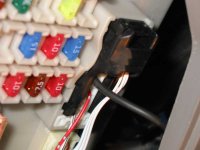
I just did this the other day as well. The only major thing I did different was I didn't splice into the ribbon wire. I ran the new wire all the way to the lower dash fuse panel. Circuit ILE has an unused pin #16 at connector 1A so I inserted a new female terminal at that location.
Thanks to Rando and all the others for the tips along the way. It works great.

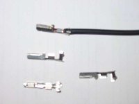
Here is the type of female terminal before the install:
 

Attachments

  • t4rmaplgt01.jpg
    t4rmaplgt01.jpg
    15.1 KB · Views: 681
Last edited:
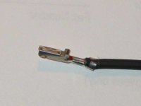
Here's the terminal (new black wire) inserted in the connector:
 

Attachments

  • t4rmaplgt02.jpg
    t4rmaplgt02.jpg
    20.6 KB · Views: 714
Last edited:
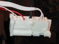
Here's the connector reinstalled at the junction block:
 

Attachments

  • t4rmaplgt03.jpg
    t4rmaplgt03.jpg
    29 KB · Views: 714
Last edited:
OMG, elite! Where did you find the right terminal?

BTW, for those that were wondering, the picture above also happens to show where the ribbon terminates at the fuse panel.
 
The second pic above shows that the ribbon terminates at pins #7, 8 & 9. Went to the wiring manual and saw pin #16 was part of ILE but not wired in the connector. Used a meter to make sure it had power but then came the hard part: finding that terminal. Everyone I asked looked at me as if WTF! Finally a local parts store guy said no problem. We search through his collection and it is close to OEM (for $2.64 ea, wire installed). Maybe the stealers have them but I would rather give my business elsewhere.
 
So you drug the parts guy out to your truck so he could see one of the existing terminals? What store was it?
 
Almost...

but lucky for him I had taken a dig pic of the existing terminals. I also completely removed the terminal retainer out of the connector block and took that in with me so that I would know that what I bought would fit.
This was a local chain auto parts wholesale counter (CWS Automotive, but try anyone that sells to the service network/garages/mechanics). I am not sure who the specific supplier is but their code for this was #300-580 in the catalog. This cross referenced to a Ford (ughh...never thought I would have to use that word) part #E8UB-14474-BA. I may still look around some more (or break down and see what the Toyota stealership has) because although it is the right size and fit it doesn't hold in the retainer. You can pull it out slightly and break the connection. I want to make it stock permanent so it can't possibly vibrate loose.
Hope this helps. On to the fog light mod. I'm still wondering about a Toyota LED rear tail-light bulb if anyone knows? I'll jump back to that thread now.
 
Last edited:
Update on wiring terminal...

Found out the stock terminals with wire from the stealer are C$8.37 each! The original terminal I found with short 16ga wire (C$2.64 ea) comes from an outfit in Guelph, Ontario called SPM Industries (and is distributed by CWS Automotive.) I needed a few more for the rear light mod but they were out of stock. So I found the raw terminal (no wire) at a GM dealer in town for C$2.25 ea. It doesn't have a true GM part # but is a Packard Connectors #7116-1472. See pic below. These are identical ends but are not a pure fit for the Toy connector. They are the right size to fit the slot but they don't clip and hold in place. Solved that by taping them in.
Maybe GM guys around you can help out if you need these. Sorry about the (lack of) focus.
 

Attachments

  • t4rrearlgt17.jpg
    t4rrearlgt17.jpg
    13.8 KB · Views: 678
Last edited:
Blade Fuse taps

rando said:
OMG, elite! Where did you find the right terminal?

BTW, for those that were wondering, the picture above also happens to show where the ribbon terminates at the fuse panel.

You can get a blade fuse tap from radio shack for a $1.49. After you crimp your wire into it (I solder it as well for security), they are made to be inserted into a blade type automotive fuse for power tapping purposes.

I just found these a week ago while picking through a parts drawer for something else.

http://www.radioshack.com/search.asp?find=ATC+Fuse+Tap&hp=search&SRC=1&image1.x=30&image1.y=34
 

Members online

Forum statistics

Threads
278,309
Messages
3,554,068
Members
248,016
Latest member
Advally Service

Trending content

Back
Top