TonyB66's Ownership -> Build Thread (2000 Limited)

The same four gauges, but in the same order though?
Nope! But there's no right answer there.

Calibrating the MPG just takes a few seconds at each fill up - though I suppose it could get a bit more complicated depending on if you need to account for tire size (I have that done separately, before the cluster and ECU).

-Charlie
 
I've always wondered how to calculate this. Not mathematically speaking, but how to determine what the speedo is set to tire size-wise. My post decal shows 225/75/R15, but when I got the truck it had 16" factory. If I go by the door post decal, that would be nearly 15% difference in size from the current tires (285/75/R16). I can confirm via TorquePro that the speedo is not that far off. Usually it's no more that 4-5 mph off when at 70 mph. Generally, I add about 10% to my tripometer to manually calculate my mpg, which always seems to be around 12-15 mpg.
 
Nope! But there's no right answer there.

Calibrating the MPG just takes a few seconds at each fill up - though I suppose it could get a bit more complicated depending on if you need to account for tire size (I have that done separately, before the cluster and ECU).

-Charlie

Starting to remember what I played with before, what settings I tweaked to get mpg dead-on, confirmed with several fill-ups not requiring adjustments. I'll get there. For now, even off, it's serves as a baseline for me, sort of like a dyno not being the most accurate, but so long as it's consistent (same dyno, procedure, operator, etc), the all important deltas can be identified.

On my SG2, I took, for me at least, a sequential approach:

1. First, top left, the air temps in the intake manifold.
2. Top right, engine coolant temps
3. Bottom left, the auto tranny temps, managed by the coolant (at least from the factory)
4. MPG, my only non-temp gauge
 
My post decal shows 225/75/R15, but when I got the truck it had 16" factory. If I go by the door post decal, that would be nearly 15% difference in size from the current tires (285/75/R16)
Basically ALL 3rd gen door stickers show the 225/75-15 tires. Since you have an SR5 4X4, is is basically guaranteed that you actually have a 16" wheel truck (speedo/gears for a 265/70-16 tire). The factory speedo displays a few MPH slow at 70mph. With your larger tires, everything sounds about right.

I had to apply a 12% correction to my (actually) 15" wheel truck with a speedo healer with the 265/70-17's that I run. That got my speedo to read exactly like factory. 67mph on speedo = 65mph actual.

-Charlie
 
Basically ALL 3rd gen door stickers show the 225/75-15 tires. Since you have an SR5 4X4, is is basically guaranteed that you actually have a 16" wheel truck (speedo/gears for a 265/70-16 tire). The factory speedo displays a few MPH slow at 70mph. With your larger tires, everything sounds about right.

I had to apply a 12% correction to my (actually) 15" wheel truck with a speedo healer with the 265/70-17's that I run. That got my speedo to read exactly like factory. 67mph on speedo = 65mph actual.

-Charlie

Thanks! #threadhighjackover
 
White with black stripe is almost always ground on Toyotas. The other wire will be power.

-Charlie

Well, green is power, at least on the passenger side marker light.

Ylglujk.jpg


How to best patch into it, I'm pondering... Not a fan of those snap connectors that splice into the wire, but here I have little to work with, about 6". The wire looks to join a larger loom that goes in front of the radiator to the other side.

I think I might snip-off the connector to this marker and solder in a segment with a lead coming off it...
 
I would suggest removing the pins in the connector and then splicing it along the wire and heat shrinking it:

qLPIvhJ.png


cABMgpd.jpg


This is my preferred method on wiring exposed to the elements.
 
I would suggest removing the pins in the connector and then splicing it along the wire and heat shrinking it:

qLPIvhJ.png


cABMgpd.jpg


This is my preferred method on wiring exposed to the elements.

Scott, I appreciate you chiming-in again. I like your thinking.

If indeed these marker lights run-off the 10A "tail" fuse in the engine bay, I might go that route.

Thoughts?

I will first confirm that's the correct fuse, and if so, I'm inclined to take that path.
 
Last edited:
If indeed these marker lights run-off the 10A "tail" fuse in the engine bay, I might go that route.

59491d1331082079-marker-corner-lights-suddenly-not-working-0306021859-jpg


Thoughts?

I will first confirm that's the correct fuse, and if so, I'm inclined to take that path.

Confirmed. They run off the 10A taillight fuse along with the license plate light.

oNxZH3T.png


Scott, I appreciate you chiming-in again. I like your thinking.

IMHO, this is the only way to do it that will really stand the test of time. All those plastic splice dealies are just going to either come lose and/or break at some point. Throwing some solder on it too is also a good idea.
 
Last edited:
cABMgpd.jpg


This is my preferred method on wiring exposed to the elements.
That is basically how I do it. Use a good stripper, expose enough wire to wrap, solder, then liquid electrical tape over the joint. No cutting of the stock wire.

In that location, I cut back the vinyl sheath first, do the work, the zip tie the cover back over the work for physical protection.

-Charlie
 
Confirmed. They run off the 10A taillight fuse along with the license plate light.

oNxZH3T.png


IMHO, this is the only way to do it that will really stand the test of time. All those plastic splice dealies are just going to either come lose and/or break at some point. Throwing some solder on it too is also a good idea.

That is basically how I do it. Use a good stripper, expose enough wire to wrap, solder, then liquid electrical tape over the joint. No cutting of the stock wire.

In that location, I cut back the vinyl sheath first, do the work, the zip tie the cover back over the work for physical protection.

-Charlie

Thank you both. I have a couple containers of liquid electrical tape. Great stuff.

That said, I'm leaning toward this approach.

5w6Krt2.jpg


Simply remove the 10A fuse, insert the Add-A-Circuit in that location with that 10A fuse in the bottom position of the AAC. Any reason not to go that route? I'd snip-off the blue crimp connector and solder and heat shrink the hot lead, run that down to the bumper, split into two, one for each side...

This cover has seen better days.

ezJy2YW.jpg


I'll keep my eyes open for a replacement... Anyone make a sticker or decal for this box?
 
Last edited:
That said, I'm leaning toward this approach.

5w6Krt2.jpg


Simply remove the 10A fuse, insert the Add-A-Circuit in that location with that 10A fuse in the bottom position of the AAC. Any reason not to go that route? I'd snip-off the blue crimp connector and solder and heat shrink the hot lead, run that down to the bumper, split into two, one for each side...

I mean, that's not the way I would do it, but it will work. I guess if you're worried about tapping into the existing wiring this would be one way to do it. Alternatively, adding a separate fuse panel for things like this would be another.

From looking at your build thread it sounds like you'll be adding other lights, but I don't recall if you've added another fuse panel. If you did (or do), you could use that lead to switch a relay that would then switch power from the other fuse panel to power these LED halos with your running lights. TIMTOWTDI!
 
Another super clean way to do this (though a bit more time consuming) is to make use of the empty fuse slots in the fuse box (like the one between TAIL and AC fuses, or the two between FOG and DEFOG fuses).

That way you are not cutting/splicing anything, and are not piggybacking on any other fuse. And it looks completely OEM.

A lot of folks (myself included) add an auxiliary fuse box without realizing that OEM fuse boxes often have empty slots that can be used.
 
Thank you both for your thoughts. Good stuff.

Yes, I prefer the fuse box approach, for a couple reasons. If for whatever reason I want to remove or even revert to stock, that cleanly allows for such. The Add-A-Circuit I believe will be quicker, for me at least, compared to connector removal and soldering there at the truck.

Leon, thanks for bringing this up - the upside of our factory box. I honesty had only removed that lid once before, I believe the day after I brought it home. That's what I'd like to do, so thanks again.

So far, for lights "added":

1. Front turn signals - Due to bumper change, replaced factory turn signals with 2" round LED ones (also a reflector).

2. Front turn signals 2 - Added rectangular turn signals on bumper fill plates below headlights

++++++ No circuits added for those above++++++

Lights to be added or connected soon:

3. Front marker light 1 - same 2" round LEDs as #1

4. Front marker light 2 - "angel eyes" around the fog lights

5. Baja Designs Wide Cornering Ambers (4A draw for the pair)

6. Baja Designs Driving / Combo white (4A draw for the pair)

7. Not yet decided/purchased, pair of spot beams or light bar

8. Rock lights (6?)

9. Pair of rear lights (likely a pair of Amazon Nilights I've had for a while)

++++++ 5-9 above to not make use of existing circuitry++++++

While I really like Leon's idea, part of me also likes the idea of one circuit for all marker/running lights, which are on the "Tail" 10A fused circuit. Using the AAC allows for such. The opens in the fuse box that Leon references will be perfect for items 5-9 and also a tranny cooler fan, and one dedicated to my ham radio. I believe three circuits would suit these needs perfectly.

Any good how-tos or posts on how to make use of these empty slots on our 3rd gen? I recall having done this before with a different vehicle and there was a way to create enough slack to flip the box over make the necessary connections...

Thanks again!
 
Last edited:
Any good how-tos or posts on how to make use of these empty slots on our 3rd gen? I recall having done this before with a different vehicle and there was a way to create enough slack to flip the box over make the necessary connections...

Thanks again!

Hey Tony, here is my writeup on how I did this - Using empty slots in OEM fuse box?. Let me know if you have more questions.

I should add that if you are planning on running a bunch of new circuits, then it may make more sense to add an auxiliary fuse block instead of messing around with the empty slots in the factory fuse box. Each approach has pros and cons :).
 
Last edited:
Hey Tony, here is my writeup on how I did this - Using empty slots in OEM fuse box?. Let me know if you have more questions.

I should add that if you are planning on running a bunch of new circuits, then it may make more sense to add an auxiliary fuse block instead of messing around with the empty slots in the factory fuse box. Each approach has pros and cons :).

Wow Leon, good stuff. I don't recall seeing that thread.

Agreed, and why forecasting future needs is pretty important, I feel. I've come to believe that 3 additional circuits is what I need:

1. various lights
2. various lights (less draw than 1), plus transmission cooler fan
3. ham radio

The engine bay fuse box should work great for those needs.

Of note, mostly to myself so I don't forget... since I decommissioned the moonroof motor and sold the factory power seats, I have power in those 3 locations. I believe all are on the same circuit, 30A, I think it also includes the power door locks... I have plenty of overhead on that circuit for future fuse.

I need some of those terminal ends. Don't see anything like that on Amazon, so will likely use what you purchased.

Mini flat type Type fuse Terminal Duplicate L size AVS3.0-5.0 - hi-1000ec.com

Or, I might make a salvage yard run like yourself...

Thanks again!
 
I need some of those terminal ends. Don't see anything like that on Amazon, so will likely use what you purchased.

Mini flat type Type fuse Terminal Duplicate L size AVS3.0-5.0 - hi-1000ec.com

Or, I might make a salvage yard run like yourself...

You definitely won't find those terminals on Amazon. If you order from hi-1000ec, their prices are dirt cheap and the shipping is extremely reasonable (considering they're coming from Japan) if you're not in a hurry and specify the LetterPost rate. But you can also get the pigtails from a junkyard like I did, just depends how much time you want to invest in the whole project.
 
You definitely won't find those terminals on Amazon. If you order from hi-1000ec, their prices are dirt cheap and the shipping is extremely reasonable (considering they're coming from Japan) if you're not in a hurry and specify the LetterPost rate. But you can also get the pigtails from a junkyard like I did, just depends how much time you want to invest in the whole project.

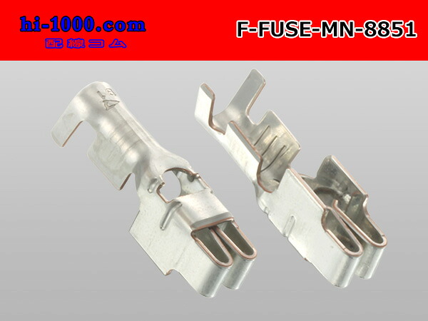
I'll take a good luck at that fuse box soon to better understand those terminals. Finding them domestically doesn't look so easy. Think this would work for a single?

f-fuse-mn-8851-1.jpg


https://global.rakuten.com/en/store/auc-hi-1000/item/f-fuse-mn-8851/

I had some time to solder some connectors...

vXB83xo.jpg


AaNdMLw.jpg


Will get some more done soon... These arrived today.

5cl9RP4.jpg


I should have some time tomorrow to install the new steering rack guide, and possibly get the alignment done after an airport run on Saturday...

Oh, forgot.... Sold my old wheels/tires for $350. Now at $1,575 in items sold...

$400 - Leather Front Seats

$50 - Factory Stereo & Amp

$75 - Cargo Privacy Cover

$50 - Skid Plates (2)

$150 - Rear Bumper

$25 - Spare Tire Crank

$200 - Front Bumper

$50 - Roof rack cross members

$50 - Front bumper carrier

$75 - Trailer hitch

$100 - Front shocks

$350 - Wheels/tires
 
Last edited:

Members online

Forum statistics

Threads
278,316
Messages
3,554,120
Members
248,016
Latest member
Advally Service

Trending content

Back
Top