Grinch
New member
Hey guys,
First, I've been reading this website's forums a lot lately and it's been very helpful in a number of areas, so thanks in advance for all the great feedback and help.
I have a 4th gen 2004 SR5.
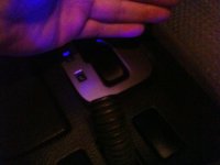
Here's the scoop: after reading through some of the cool shifter knob forums, I thought I was going to get one of the Lexus ones, but my wife said to look for something like Transformers or Bit from Tron. I saw some decent custom Transformers ones, but didn't see anything for Bit from Tron....but after looking at Tron I got the idea to do it from the old school Tron arcade game joystick. So the goal is to get that baby mounted as my shift knob and have some black lights pointed at it to light it up! I'm going to post some pics and the steps I've taken so far, and the then the finale ones in one day after the JB Weld have cemented the other side. The main question I have and kind of the reason I'm posting is I need to have the 3 LED black (UV) lights pointed at the joystick. They are coming out of one of those center tab/spacers right behind the shifter where I guess the DAC switch would usually be (what's the technical term for the tab/spacer btw???). I'd like to have kind of an "L" shape for them so that they point at the joystick, but is covered up with some kind of overhead where the driver doesn't actually see them....Any ideas?...and now for the steps I've done so far:
Here's the main list of items needed:
Tron controller (Groovygamegear.com), trigger(Groovygamegear.com), Tron insert(just Google and you'll find), JB Weld (Home Depot), 2 3/8" washers, 1 M8x1.25 hex nut, 3 UV 5mm LEDs (Radio Shack...note that these are 3.2v-3.8v max), Cigarette Lighter car power adapter that takes 12v down to 3v (Radio Shack), 12v cigarette lighter accessory outlet (Radio Shack)
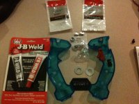
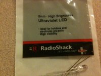
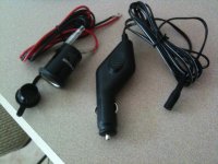
Sorry I didn't take pics of the JB Weld stuff, but:
--JB Weld the 2 washers and the nut together. Try and make sure they are not overlapping and they are all even. You're going to be putting the nut on top of the two washers, so it goes: washer, washer, nut. It seemed like the nut only went on one way when I was screwing it into the gear shift stick, so make sure you have the right side on top. The nut will be on top closest to the trigger <see next post for pic of what I'm talking about>. Wait 15 hours for the Weld to get good and tight.
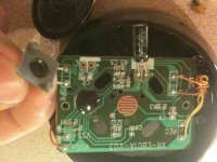
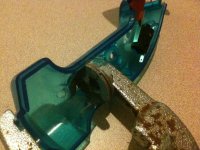
--After the 2 washers and nut are best friends, you're going to JB Weld them into the right half of the Tron joystick. This is because it's the side that is harder to get the washers into and you have to squeeze it into place to make it line up with the little grooves where the screws are supposed to go...again, see next post for pick of what I'm talking about. I actually tried to hold it in place forever, and it kept busting back out, so I got a wrench and am clamping it down that way so it stays in place overnight. Wait 15 hours.
--Put some more JB Weld on the washers and stick on the other side of the joystick. At this point, you're taking the rubber band off the trigger and putting the Tron insert in as well. Let it sit for 15 hours again.
--Assuming all lighting is done, just screw it into the the gear shift stick...that's my plan any way ...moving on to lighting.
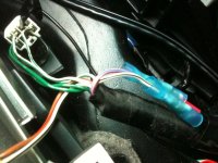
I tapped into some extra cable that was under the plastic where the shifter is. It was taped up next to the cigarette lighter cable. I read in another thread that the pink with blue stripe cable was power and that the W/B was ground, so I just cut those two wires from that connector and crimped and heat shrinked those guys together to the accessory outlet after running the accessory outlet's cable from my center console into the area where the shifter is (I had a hole there I had created when I was putting in my XM stuff). W/B went to the black wire and P/B went to the red wire.
Now it was time for the LEDs. I cut some cables to solder to the LEDs to then connect altogether into a heat shrinked connector to the cigarette lighter adapter. See pic for what I used.
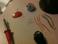
The longer cable for the LEDs is the positive...I may be wrong, but one blew up on me when trying it the other way, so I just played it safe and considered that the positive and connected some 16 gauge??? wires to each side...I used red for positive and black for negative...soldered them to the LEDs.
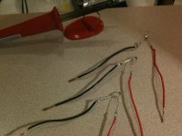
I ran the cigarette lighter adapter's black and black/white cables through that hole out of the center console into the shifting area. I then took all 3 red lines from the LEDs and twisted them together, put them into one of the heat shrink crimp connectors that connected to the black cable of the cigarette lighter adapter (OH YA, I FORGOT TO MENTION I SNIPPED OFF THE END OF THE WIRED WHERE THE 2 FEMALE PORTS ARE ON THAT ADAPTER IN ORDER TO EXPOSE THE WIRES TO STRIP AND CONNECT TO). I did the same for the black wires for the LEDs but connected them to the black/white cable of the adapter.
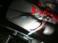
Then I just connected the cig lighter adapter into the accessory outlet (they're both in my center console), and boom, UV lights. I also have the ability to turn them off anytime I want too by just unplugging it from the outlet.
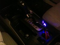
I'll post the pics of the joystick when done and in the car. Right now, if someone would be so kind as to give some suggestions on how to have something fit in that center spacer tab where the DAC switch usually is; that will cover the lights but allow me to point them towards the shifter, it would be most appreciated. I'm think of something like bendable aluminum that would hover over from the little tray behind it sitting there by some sticky tape?...
Thanks.
First, I've been reading this website's forums a lot lately and it's been very helpful in a number of areas, so thanks in advance for all the great feedback and help.
I have a 4th gen 2004 SR5.
Here's the scoop: after reading through some of the cool shifter knob forums, I thought I was going to get one of the Lexus ones, but my wife said to look for something like Transformers or Bit from Tron. I saw some decent custom Transformers ones, but didn't see anything for Bit from Tron....but after looking at Tron I got the idea to do it from the old school Tron arcade game joystick. So the goal is to get that baby mounted as my shift knob and have some black lights pointed at it to light it up! I'm going to post some pics and the steps I've taken so far, and the then the finale ones in one day after the JB Weld have cemented the other side. The main question I have and kind of the reason I'm posting is I need to have the 3 LED black (UV) lights pointed at the joystick. They are coming out of one of those center tab/spacers right behind the shifter where I guess the DAC switch would usually be (what's the technical term for the tab/spacer btw???). I'd like to have kind of an "L" shape for them so that they point at the joystick, but is covered up with some kind of overhead where the driver doesn't actually see them....Any ideas?...and now for the steps I've done so far:
Here's the main list of items needed:
Tron controller (Groovygamegear.com), trigger(Groovygamegear.com), Tron insert(just Google and you'll find), JB Weld (Home Depot), 2 3/8" washers, 1 M8x1.25 hex nut, 3 UV 5mm LEDs (Radio Shack...note that these are 3.2v-3.8v max), Cigarette Lighter car power adapter that takes 12v down to 3v (Radio Shack), 12v cigarette lighter accessory outlet (Radio Shack)
Sorry I didn't take pics of the JB Weld stuff, but:
--JB Weld the 2 washers and the nut together. Try and make sure they are not overlapping and they are all even. You're going to be putting the nut on top of the two washers, so it goes: washer, washer, nut. It seemed like the nut only went on one way when I was screwing it into the gear shift stick, so make sure you have the right side on top. The nut will be on top closest to the trigger <see next post for pic of what I'm talking about>. Wait 15 hours for the Weld to get good and tight.
--After the 2 washers and nut are best friends, you're going to JB Weld them into the right half of the Tron joystick. This is because it's the side that is harder to get the washers into and you have to squeeze it into place to make it line up with the little grooves where the screws are supposed to go...again, see next post for pick of what I'm talking about. I actually tried to hold it in place forever, and it kept busting back out, so I got a wrench and am clamping it down that way so it stays in place overnight. Wait 15 hours.
--Put some more JB Weld on the washers and stick on the other side of the joystick. At this point, you're taking the rubber band off the trigger and putting the Tron insert in as well. Let it sit for 15 hours again.
--Assuming all lighting is done, just screw it into the the gear shift stick...that's my plan any way
...moving on to lighting.I tapped into some extra cable that was under the plastic where the shifter is. It was taped up next to the cigarette lighter cable. I read in another thread that the pink with blue stripe cable was power and that the W/B was ground, so I just cut those two wires from that connector and crimped and heat shrinked those guys together to the accessory outlet after running the accessory outlet's cable from my center console into the area where the shifter is (I had a hole there I had created when I was putting in my XM stuff). W/B went to the black wire and P/B went to the red wire.
Now it was time for the LEDs. I cut some cables to solder to the LEDs to then connect altogether into a heat shrinked connector to the cigarette lighter adapter. See pic for what I used.
The longer cable for the LEDs is the positive...I may be wrong, but one blew up on me when trying it the other way, so I just played it safe and considered that the positive and connected some 16 gauge??? wires to each side...I used red for positive and black for negative...soldered them to the LEDs.
I ran the cigarette lighter adapter's black and black/white cables through that hole out of the center console into the shifting area. I then took all 3 red lines from the LEDs and twisted them together, put them into one of the heat shrink crimp connectors that connected to the black cable of the cigarette lighter adapter (OH YA, I FORGOT TO MENTION I SNIPPED OFF THE END OF THE WIRED WHERE THE 2 FEMALE PORTS ARE ON THAT ADAPTER IN ORDER TO EXPOSE THE WIRES TO STRIP AND CONNECT TO). I did the same for the black wires for the LEDs but connected them to the black/white cable of the adapter.
Then I just connected the cig lighter adapter into the accessory outlet (they're both in my center console), and boom, UV lights. I also have the ability to turn them off anytime I want too by just unplugging it from the outlet.
I'll post the pics of the joystick when done and in the car. Right now, if someone would be so kind as to give some suggestions on how to have something fit in that center spacer tab where the DAC switch usually is; that will cover the lights but allow me to point them towards the shifter, it would be most appreciated. I'm think of something like bendable aluminum that would hover over from the little tray behind it sitting there by some sticky tape?...
Thanks.











 interested to see where you go with this