Br1ck
Well I'm looking at the electrical wiring diagram book for the 2003 4R the 6 speaker has the same harness to the rear seat audio controller as 10 speaker system, so whichever you have should be the same as this.
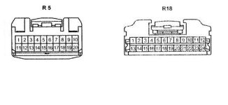
On the back of the radio is there should be 2 20 plugs, if I remember correctly one is plug R5 shown below (all pins are the same size) This is a view of the plug from the front (business end) where it plugs into the radio. I also show a pictorial of the plug on the controller. I have not actually seen this plug, I have to trust the manual.
Here is the pinout. Refer to the attached diagram of the plugs involved:
Plug R5 (is at the radio in the dash)
Audio uses pins 14-18 as follows
Pin 15=RSR+, Pin 16=RSR- (that’s your right channel audio)
Pin 17=RSL+, Pin 18=RSL- (that’s left channel audio)
Pin 14 is the audio shield which should be at ground potential.
Pin 19 is RMU
Pin 6 is Mute
Pin 9 is TX+ (suspect this is a control line but not sure if its sends data to rs controller or data is sent from the rear seat controller).
Pin 10 is TX- (suspect this is a control line going the other direction.)
Plug R18 ( is at the Rear seat controller-dome light)
Pin 6=RSL-, Pin 7=RSL+
Pin 8=RSR-, Pin 9=RSR+
Pin 10 is the audio shield.
Pin 17 = GND on the controller connector R18.
Pin 22 = TX+
Pin23 = TX-
Pin 24 = ACC on the controller connector R18.
Pin 12 = 12VDC
The system audio uses a balanced feedline so there are actually two signal lines for each channel plus a common signal ground. If your new system uses a standard unbalanced line, try connecting the signal lines to either the + or – but not both on each channel and the ground to the shield.
I have not done any mods with the rear seat controller so use caution, you are on your own.
GL -TM-