Use OEM IR in dome for Aftermarket Video

Br1ck

New member
Ok, so I've got my rear video working but now I want to add IR wireless headphones. I've got an old IR transmitter and Sony headphones that I can use, but I'd like to tap into the OEM IR transmitter that is already part of my dome light.

Anyone have the wiring diagram for that? It would seem to me that all I have to do is tap into wire that sends to the audio to the transmitter, then it would take care of converting and transmitting it...:dunno:

What do you think?
 
Register to hide this ad
Why not just use the existing OEM transmtter in the dome light? It would probably make for a neater install. I think I may have missed something here.

I am sure I have the wiring info somewhere, so I will try and help out a bit later today.

Regards -TM-
 
Toy-Man,

You're right...I want to use the existing IR transmitter. What I'm looking for is somebody who might know how I can tap into dome light and send my own audio signals.

I hope you've got something that might help.
 
Br1ck

Well I'm looking at the electrical wiring diagram book for the 2003 4R the 6 speaker has the same harness to the rear seat audio controller as 10 speaker system, so whichever you have should be the same as this.

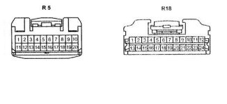
On the back of the radio is there should be 2 20 plugs, if I remember correctly one is plug R5 shown below (all pins are the same size) This is a view of the plug from the front (business end) where it plugs into the radio. I also show a pictorial of the plug on the controller. I have not actually seen this plug, I have to trust the manual.


Here is the pinout. Refer to the attached diagram of the plugs involved:

Plug R5 (is at the radio in the dash)

Audio uses pins 14-18 as follows
Pin 15=RSR+, Pin 16=RSR- (that’s your right channel audio)
Pin 17=RSL+, Pin 18=RSL- (that’s left channel audio)
Pin 14 is the audio shield which should be at ground potential.
Pin 19 is RMU
Pin 6 is Mute
Pin 9 is TX+ (suspect this is a control line but not sure if its sends data to rs controller or data is sent from the rear seat controller).
Pin 10 is TX- (suspect this is a control line going the other direction.)

Plug R18 ( is at the Rear seat controller-dome light)

Pin 6=RSL-, Pin 7=RSL+
Pin 8=RSR-, Pin 9=RSR+
Pin 10 is the audio shield.
Pin 17 = GND on the controller connector R18.
Pin 22 = TX+
Pin23 = TX-
Pin 24 = ACC on the controller connector R18.
Pin 12 = 12VDC


The system audio uses a balanced feedline so there are actually two signal lines for each channel plus a common signal ground. If your new system uses a standard unbalanced line, try connecting the signal lines to either the + or – but not both on each channel and the ground to the shield.

I have not done any mods with the rear seat controller so use caution, you are on your own.

GL -TM-

 

Attachments

  • r5 r18.jpg
    r5 r18.jpg
    26.9 KB · Views: 472
Last edited:
Toy-Man,

This some awesome info. Now, I just need to soak it in and figure out exactly what to do next. Not sure what I was hoping for, but I did want to use my stadard RCA interconnects to pull this off...maybe I can, but now I need to think about this a bit more.
 
Quick question: Does every 4th Gen model have this built into it? And it would be a matter of tapping into the line? I bought a RF unit just because I did not want to try to pull off the lining, But I am not happy with the quality of sound.
 

Members online

Forum statistics

Threads
278,316
Messages
3,554,121
Members
248,016
Latest member
Advally Service

Trending content

Back
Top