Wacky Instrument Cluster Issue

I'll throw a random WAG into the mix. It sounds like a relay (or a computer)
gets stuck and interrupting power lets it open (or close) again. I have not
dug out wiring diagrams in an attempt to figure out where that might be
happening. I don't have that kind of attention span :faint:
 
That was similar to my thinking because small shorts and bad grounds are relatively unaffected by shutting off power and turning it back on. Devices with logic are. And relays I suppose.

I noticed a small relay on the body ecm - swapped that out with the power outlet one under the hood, power outlet still works however - but could have been intermittently sticking?

If that doesn't do it, I'm thinking next step is to replace the body ecm all together.

Fun fun fun
 
This is a rough one. The factory wiring diagrams don't go into much detail on the gauge cluster. There is a secondary black box shown internal to the gauge cluster that connects to all the subsystems that you describe as going out when the error happens, but there is no information on it. Do the door locks, dome light(s) and headlights all work the same when the problem happens (they are also connected there).

I'm having trouble coming up with a possible scenario that could explain why the truck is causing the gauge cluster error...

-Charlie
 
Thanks for looking into this!!

All locks and I believe lights work when it happens. Definitely head lights/dimmer

Happened again today close enough to home to safely make it without fixing it. I found that pulling the 15 amp DOME fuse has the same effect as taking the battery negative terminal off and back on. It fixes it just like the battery method.

Not sure if this gets us any farther???

Guess its something on the DOME circuit?

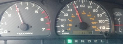
The pic is what it looks like when it happens, first time uploading pics please let me know if it works.

Thanks!
 

Attachments

  • 0715191846.jpg
    0715191846.jpg
    136.6 KB · Views: 846
Does anyone have downloadable copies of the instrument cluster wiring diagram?

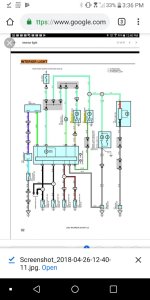
I've been using this one which shows the 15 amp DOME fuse circuit. Just checked the sunroof and dome lights as well as the door courtesy switches.

Does the cluster receive power only from the DOME circuit? Or from other places once the engine is started.

Still scratching my head
 

Attachments

  • Screenshot_2019-07-16-15-36-50.jpg
    Screenshot_2019-07-16-15-36-50.jpg
    125.5 KB · Views: 936
Is the body ECU on the DOME fuse?
The body ECU has connections to many fuses - MPX-B, ECU-IG, POWER, HORN, WIPER, ACC and probably others.

You are on to something here through - it might be worth trying to remove individual fuses instead of the battery main ground to try to see which one resets the cluster.

A replacement body ECU might be worth trying to see if that can do it too - I did finally find one direct connection between the Body ECU and the Gauge Cluster (Combination Meter) on the multiplex communication bus pages of the diagrams - it look like it could be some sort of communication between the two.

-Charlie
 
Ok. I think I will be sourcing a body ECU.

While I'm at the yard, what other parts should I pull?

Where are the other ecus?

Maybe I'll pull a third cluster lol

Help
 
Does anyone have downloadable copies of the instrument cluster wiring diagram?

I've been using this one which shows the 15 amp DOME fuse circuit. Just checked the sunroof and dome lights as well as the door courtesy switches.

Does the cluster receive power only from the DOME circuit? Or from other places once the engine is started.

Still scratching my head
From the 2000 EWD manual.
 

Attachments

Thank you Durk.

Trying to decide what the diagrams tell me given my symptoms.

Think it could be something on p 229 because that contains all the affected gauges.

Water temp gauge is on next page and is not affected when my problem happens.

That said, what should I look for??

Not used to electrical diagrams (teenager)

Thanks again
 
Thank you Durk.

Trying to decide what the diagrams tell me given my symptoms.

Think it could be something on p 229 because that contains all the affected gauges.

Water temp gauge is on next page and is not affected when my problem happens.

That said, what should I look for??

Not used to electrical diagrams (teenager)

Thanks again

Honestly, your symptom set is pretty off the wall. And, as Charlie said, the diagrams are not meant to give detail on the internal wiring of units. My guess on this is you have an intermittent fault (wiring short?) on one of those gauge inputs outside the module that kicks the module into some kind of safe mode. Intermittents are a pain. I would look over the wiring to the speed sensor to start with and then the other affected gsuge inputs.
 
Thank you Durk.

Trying to decide what the diagrams tell me given my symptoms.

Think it could be something on p 229 because that contains all the affected gauges.

Water temp gauge is on next page and is not affected when my problem happens.

That said, what should I look for??

Not used to electrical diagrams (teenager)

Thanks again
228 and 229 are where all your problems are happening, all are connected to that inner box inside the gauge cluster that probably represents the logic board attached to the back of the cluster:

P0P0sQO.jpg


The connectors C27 (E) and C28 (D) in the diagrams are the white and blue ones on the "MAIN PCB1" above. Since you changed gauge clusters and the problem persists, it likely isn't the cluster itself, but how it is interacting with the rest of the truck.

The connection now that concerns me is the G-W wire on page 228 that is "From Body ECU" - there is no description of how/what that wire does - but if it is some sort of communication, that may be the problem.

-Charlie
 
Ok thanks. I will get a 99 or 00 body ECU from the yard.


Where is the speed sensor located? I thought 3rd gens get that info from the wheel (ABS) sensors.

If they're still on the one i pulled the cluster from, ill get the sensors too.

What else should I pull off the donor yard 4runner that might be related?

Strange how no one has ever heard of this happening...
 
Ok thanks. I will get a 99 or 00 body ECU from the yard.


Where is the speed sensor located? I thought 3rd gens get that info from the wheel (ABS) sensors.

If they're still on the one i pulled the cluster from, ill get the sensors too.

What else should I pull off the donor yard 4runner that might be related?

Strange how no one has ever heard of this happening...

On a 5-speed they do. I don't know about autos. There is one on the EWD.

Here is the Combo meter inspection chapter from the 2000 FSM. You might consider doing the tests in the first part which are tests of the truck, not the module. If something is out of spec, it might be a clue.
 

Attachments

I had all my gauges, odo and ABS completely die on my 2001. Also got a CEL and running a reset through the diagnostic plugs came up short. Turned out to be the ABS ECU was dead. It’s different for 01 / 02 but replacing the whole ECU cleared my issue up after a ton of research in the FSM. It was written in very tiny print as an aside, like “if the reset doesn’t work, maybe the computer is dead?” The ABS ECU on yours is behind the passenger footwell trim panel, outboard side, iirc.

Not sure if that helps at all but may be a clue to start. I was v surprised that my odo was running through that computer, but whatever...I’ve been fixed and fine for the last 7-8 months.


Sent from my iPhone using Tapatalk
 
Where is the speed sensor located? I thought 3rd gens get that info from the wheel (ABS) sensors.
For non-ABS 4Runners, it is on the rear output of the transfer case (or transmission tailhousing if 2WD). All others use the ABS computer. A signal comes from the ABS computer to the gauge cluster (GR-L grey-blue wire), which then takes that signal and drive the speedo/odo and the rest of the truck (G-O green-orange wire).

-Charlie
 

Members online

Forum statistics

Threads
278,309
Messages
3,554,071
Members
248,016
Latest member
Advally Service

Trending content

Back
Top