What Did You Do To Your 3rd Gen Today?

Status
Not open for further replies.
Correction: I turned the crank pulley another 360 degrees to line up with zero. The cam sprocket marks are at basically 12 o'clock, but maybe 2mm off or so from the mark on the back timing cover. The marks on timing belt itself are still off, when I first installed engine I'm pretty certain they were lined up at 12 o'clock as well. Is that telling me the belt is slipping?
 
Match the crank to zero, both cams should be 12 o clock there are notch marks on the cam gears and notch marks on the metal backing plate behind the cam gears. They should line up.

If your 180 out rotate the engine again one rotation according to the crank pulley and see where the cams are.
 
Match the crank to zero, both cams should be 12 o clock there are notch marks on the cam gears and notch marks on the metal backing plate behind the cam gears. They should line up.

If your 180 out rotate the engine again one rotation according to the crank pulley and see where the cams are.

Gotcha, I rotated it again and lined up crank pulley. The cam sprockets marks are almost lined up but not perfectly. Meaning if I ran a straight edge, the cam gear tooth and backing plate marks would be about 2-3mm off. From my understanding these marks don't need to be absolutely perfect but close
 
I'd say a tiny bit off might be ok, as there is a cam sensor on the pass side cam gear. If it's a few teeth off then no dice. I've done quite a few 5vz timing belts and never had a issue with any marks not lining up. As long as you stick with a reputable manufacturer of the timing belt that is. Lately there seems to be a serious issue with quality of timing belts.
 
I'd say a tiny bit off might be ok, as there is a cam sensor on the pass side cam gear. If it's a few teeth off then no dice. I've done quite a few 5vz timing belts and never had a issue with any marks not lining up. As long as you stick with a reputable manufacturer of the timing belt that is. Lately there seems to be a serious issue with quality of timing belts.

Yeah that makes sense. The closest cam tooth, which the shop highlighted in blue, is offset by such a tiny amount to the mark I think it should still work. Assuming that's close enough would that rule out timing as an issue?
 
I'd say a hair off it should be ok, but a tooth or more, no.

Anyways we should get back on topic in this thread. If you can start up a new thread, so we can continue your diagnosing.
 
Threw the original JKC/Bendix booster back in and the pedal does indeed feel better than with the "replacement".
Now - better is by no means perfect, but it's clear the cheap versions potentially leave much to be desired.

It still stiffens up pretty good under hard braking, but it tests out ok with engine-off-pump-start-etc.
Reviewing my options for another proper replacement, but I feel it's safe to drive in the meantime.
Gonna do another bleed and service the drums, as it's been a while since they've seen much attention.

Also received the VCGs + related thingies, various coolant hoses & clamps, and some fun little tools
in preparation for some 270K service-type stuff that the ol' donkey certainly deserves.
 
Just ordered up some sherpa rack components to diy some load bar type racks for solar and traction board mounting. Didn't realize they had scratch and dent cross bars that are super cheap, like a bit over 10 bucks a bar, granted they are 47" wide (which I wanted). Super stocked, as I need to get these projects done before summer hopefully......
 
Correction: I turned the crank pulley another 360 degrees to line up with zero. The cam sprocket marks are at basically 12 o'clock, but maybe 2mm off or so from the mark on the back timing cover. The marks on timing belt itself are still off, when I first installed engine I'm pretty certain they were lined up at 12 o'clock as well. Is that telling me the belt is slipping?
The timing belt has an odd number of teeth on purpose - it will only line up to the marks on the sprockets once every 150 or so rotations - to keep belt and sprocket wear to a minimum (each belt tooth will interface with each sprocket tooth to no patterns of wear develop).

If the sprocket/gear marks are within one tooth, you are fine from that perspective.

-Charlie
 
Followup to my poor diagnostics on the rear locker failure I had a few weeks ago: https://www.toyota-4runner.org/3852875-post35904.html

Got a new locker harness (from body to axle), plugged it in, bolted it in place, and everything is working perfectly.

It was still a confusing failure. The weak actuator that barely, then failed to lock form the dash switch, and then the way it would lock and unlock normally when manually jumpered at the rear seat connector.

In retrospect, it was still operating a bit slower than it should have when manually jumpered with a spare battery from the rear seat, but since I don't normally hear what it sounds like, I assumed it was working normally.

And I didn't catch that the unlock limit switch signal was missing when I manually locked and unlocked it. And didn't even think about the motor wires still being connected, just damaged and adding a lot of resistance.

Anyhow, all's well that ends well. Now I have a spare locker ECU and actuator.
 
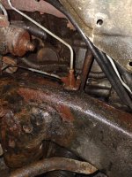
On my way to get new tires, I blew a left front brake line. Downstream hard line of the 90* "fitting". Needless to say, I limped over to an autozone to get some brake fluid to get back home.......very slowly with a lot of distance between me and anything in front.

I just got this 4Runner a week ago. PO did brakes on all 4 corners about 5K ago. But not all the lines were done. AND the parking brake needs adjustment.

A week ago, on my way back from picking it up I paid a visit to a forum member.....Brillo.

We discussed a lot of 4Runner things. One of them was fabricating brake lines. So I already had a brake line "kit" in my amazon shopping cart. I knew I was going to have to do this sooner or later. It is sooner.

So for my 4Runner today.....no new tires, cursed at her a little bit, a DIY brake line kit with 25' of 3/16" Cu-Ni tubing, amazon flex hoses and amazon hard lines from flex hose to caliper.
 

Attachments

  • LF Brake Lines.jpg
    LF Brake Lines.jpg
    140.5 KB · Views: 207
Followup to my poor diagnostics on the rear locker failure I had a few weeks ago...
<snip>
Well, continuing on with my history of stumbling around blindly on this issue, turns out the locker was NOT working properly after replacing the harness with some broken wires. I merely assumed it was because it was making HEALTHY sounding actuation noises on both lock and unlock. Back and forth. But it was miserably cold out, and I didn't bother to jack up a wheel and make sure it was actually locking and unlocking.

Turns out, it wasn't actually locking. It would make noises and move, but only for a short period, stopping short of locked. Then (from the sound) it would unlock fully when the switch was turned off.

Argh, waited until a slightly nicer day (still cold, windy, miserable, the 4Runner doesn't fit in the garage so this is done outside) and took out the locker.

Long story short - it turns out that what I was doing by jumpering 12V to the M1/M2 wires to manually lock and unlock it is VERY RISKY. The actuator, when actuated by the locker ECU, which looks at the limit switches inside the actuator, only tuns about 1/3rd of a turn. Far lass than I thought/assumed (because it has a full, round gear both inside and out, most of that isn't used!).

When jumpering it manually, the actuator will move further, almost a half turn, until it hits some mechanical stops. And apparently, it can move far enough to get past the limit switches (contacts sliding on a metal plate with holes in it) to get past where the locker ECU thinks it should be. So the locker ECU tries to lock, sees something from the limit switches that says it's already locked, and it immediately stops trying.

This certainly wasn't clear to me underneath the car. I just took it inside the house and messed about with it on the kitchen table where it was warmer. And tested my locker and the new locker by jumpering the M1/M2 wires. Turns out the new locker did even worse, it jammed and wouldn't move after moving to the mechanical limit one single time!

Anyhow, after taking it apart and looking at how it works, we figured out how the limit switches worked, and how they 'logically' limit it to a much shorter range. And repositioned my locker, and the new locker that I'd jammed, and under the car, plugged into the car harness, saw them both turning the proper 1/3rd turn back and forth. My well used one made some slightly less good noises, so I put the new one on. Made sure the diff was unlocked, repositioned the actuator back and forth a couple of times, to unlocked, and installed it. Wheel jacked up, not it is FINALLY locking and unlocking properly again.

Sheesh, what a confusing long fiasco on my part. It was a quirky failure, compounded by limited diagnostics (cold and miserable outside) and me firing off the parts cannon too quickly.

But yeah, main takeaway, manually jumpering the actuator can leave it in a position that it can't recover from, and requires removal, partial disassembly, and manual repositioning.

Almost enough to make someone want to buy one of those cable actuators, lol.

But srsly, if I'd spent the time, jacked up a wheel, and done proper diagnostics, I could have figured this out on day one.

 
But yeah, main takeaway, manually jumpering the actuator can leave it in a position that it can't recover from, and requires removal, partial disassembly, and manual repositioning.

Thanks for posting the research and findings, John! I'm sure it'll be very useful to someone down the road. A lot of things on these trucks are not as simple as they may seem at first (**cough**IAC**cough**), so this kind of diagnostic trial and error is super helpful!
 
Well, continuing on with my history of stumbling around blindly on this issue,......,i.

My first 3rd gen had a locker added after and had a harness made that used no computers, it was either on or off. It used a lighted toggle switch as it did not trigger any dash lights ( without computer). So basically hot wired.
I never had an issue with it going on or off.
so there must be a sequence on how it is hot wired but it was all plug and play.

Got mine from a company , that is no longer in business..
when looking into adding locker to 2nd 3rd gen I beleive it was yota masters that had the plug and play harness
 
My first 3rd gen had a locker added after and had a harness made that used no computers, it was either on or off. It used a lighted toggle switch as it did not trigger any dash lights ( without computer). So basically hot wired.
I never had an issue with it going on or off.
so there must be a sequence on how it is hot wired but it was all plug and play.

Got mine from a company , that is no longer in business..
when looking into adding locker to 2nd 3rd gen I beleive it was yota masters that had the plug and play harness

They still sell those, I was actually looking at them at some point in this confusing mess.
Ultimate Toyota E-Locker Wiring Harness Kit

They certainly don't have a wiring diagram. But I would hope that they are using the limit switches, instead of just constantly supplying 12V/GND (alternating for lock/unlock) to the M1/M2 terminals. The motor only needs to be powered for a brief period. It doesn't even need to actually engage or disengage the differential, it's spring loaded. The internal gear will position all the way until the limit switch signals it's far enough, then shut off. Then a CHUNKY clock spring between that and the external gear that drives the diff locker fork will hold tension until it finally mechanically moves.

Habanero homebrewed her locker wiring setup on her 96 and used a relay which shuts off in each direction when the limit switches trip. Not the locked switch, that's a separate sensor on the diff locker fork that lights when it physically moves to locked. I'd have to guess Yotamasters is doing similar. I think the motor would simply burn up if left powered for long with it not moving. Plus the issue of it moving too far when the limit switches aren't used.

In addition to flipping the current back and forth for lock/unlock, and stopping when the limit switches say so, the factory locker ECU also:
- doesn't let you lock when the car isn't in 4LO (the gray wire mod bypasses that feature)
- doesn't let you lock when the car is going faster than 5(???) mph, I left that one alone
- does the 'in progress' locker light flashing. It flashes the dash light when the locker state doesn't match the requested state, other wise all you'd get is a steady light when locked, off when trying to lock or unlocked
- in addition to cutting power when the limit switches are met, it also does something like a 4 or 5 second max time to attempt to lock or unlock. Assuming this is so if the limit switches never get met, because the mechanism is jammed or stuck somehow, it won't sent continuous power and fry something.

I put an Eaton e-locker on the front of mine, it's way more simple. The dash switch uses a relay, but it's still as simple as 12V+ to the locker, it's locked as long as the 12V+ is supplied. 12V goes off, it unlocks. Far more simple. I guess, as long as it works, lol.
 
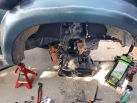
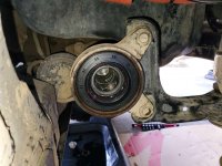
Well today I reinstalled the stock hubs, new wheel bearings, and new trackmotive extended travel cv's. Also put in arp studs instead of bolts for the lower ball joint mount. Man it's a PITA to take apart all the manual hub stuff. Those damned cone washers.

I have to take the pass side axle out of the hub as I forgot to grease the splines of the cv stub......sigh. Lost my 36mm socket to, so this will be finished tomorrow. Oh yes also put in the land cruiser hex front diff drain plug. Almost stripped the alen out.

Well, the outcome........ got an inch more down travel! That is awesome! The coilovers top out before the cv's come close to binding. Rad! No other pics, had to focus on getting this done. Still got to install the front diff breather mod thing to stop it from puking oil.
 

Attachments

  • 20250222_142302_mOl1FGhl4e.jpg
    20250222_142302_mOl1FGhl4e.jpg
    137.7 KB · Views: 108
  • 20250222_142233_QKgifKbf3y.jpg
    20250222_142233_QKgifKbf3y.jpg
    134.5 KB · Views: 110
Last edited:
Extended travels CV's for manual hubs? I didn't know anyone made those, Toyota (rebuilt) manual CV's are NLA and I thought there were just regular aftermarket CV's available now. Do you have a link for them?

EDIT: Never mind, I think I missed the first part of your post where you said you reinstalled the stock solid hubs.
 
Last edited:
Status
Not open for further replies.

Members online

Forum statistics

Threads
278,316
Messages
3,554,120
Members
248,016
Latest member
Advally Service

Trending content

Back
Top