Wiper/washer switch mist mod

sharp4runr said:
Good question. Not sure what happened to it. I remember it was quite a large thread too, which I was suprised it got so large :)

I did some searches and couldn't find it, so I'm assuming it got deleted. For what reason, who knows?

Yeah I know it is weird. I thought we were actually getting somewhere with it especially with narrowing down vehicle alternatives and figuring out possible alternative solutions.
 
00328 said:
I've purchased momentary switches at Radio Shack for equipment at work. They have a push-button type, one press gives one cycle.

Do you happen to have a part # or pic?

I tried a wiper sweep only (my Plan B) by using a larger momentary switch in the same location as the rocker switch in my current mod. Wiring a relay for this is easy but the switch wasn't convenient, "just" out of reach as an awkward location and didn't look stock. Maybe a smaller switch can be positioned in a better location up near or on the wiper stalk.
 
Last edited:
For Plan B:
I was able to find a black 1/2" diameter Momentary Push-Button Switch at The Souce (Radio Shack.) It is #2750644 rated at 3A@120VAC (maybe someone can clarify if this is OK for use with 12VDC.) You can mount this switch in the steering wheel trim (maybe near the base of the wiper stalk) if you wanted to go the route of a single sweep mist button. You can wire this up to a relay with power from the driver's side fuse box, a new ground, and use the Blue and Blue/Black stripe wires (mentioned earlier) to complete the circuit to switch the wiper momentarily on/off. All this wiring can be done within the same harness and area I worked in previously.

Personally, I've had a few days to use the Plan C method with the rocker switch. I got quite comfortable with using the new wiper mist+ function in some extended driving in wet snow, where the intermittent wipers would have been too frequent. I like this method plus I don't use the washer on a regular basis. I plan to stick with this mod as is, except as mentioned, I'll be upgrading the switch.
 
Last edited:
This is all great information, but I'd much rather find a way to increase the maximum delay time on the intermittent wipers. If the delay were longer, I wouldn't really need the "mist" feature of the wipers.
 
Even Steven said:
... but I'd much rather find a way to increase the maximum delay time on the intermittent wipers...

I hear you, but we need an electronics wiz.

The easy part:
Take your steering column trim off (as above.)
Disconnect the wiring harness connector from the bottom of the wiper/washer switch.
Remove 2 small brass Phillips head screws, above and below the stalk, holding the black switch package in it's white plastic track.
Slide the switch out to the right.
Holding the switch in your hand, remove the back white plastic cover (by flexing the clip retainers) to expose the circuit board.

Now the hard part:
Figure out how to modify the intermittent timer on this circuit, because I'm lost when it comes to playing around with this stuff.
 
Last edited:
SOMETIMES there is a 'pot' (usually a very tiny screw) that can be adjusted on the circuit board. But that would just be too easy.
 
00328 said:
SOMETIMES there is a 'pot' (usually a very tiny screw) that can be adjusted on the circuit board. But that would just be too easy.

That would be too easy.... but I know exactly what you mean. A "pot" is a potentiometer....better known as a variable resistor. If the guys who created the circuit wanted to make the delay adjustible, they could have easily used a pot. But I doubt they ever had that in mind in the first place, so I'd be surprised to see one there....
 
I would try larger capacitors replacing the one that connects to pin 16. I'd do it myself but am still healing from back surgery.
 
drmorbius said:
I would try larger capacitors replacing the one that connects to pin 16. I'd do it myself but am still healing from back surgery.

Do you have a schematic for the wiper switch circuit board?
 
Even Steven said:
Do you have a schematic for the wiper switch circuit board?

I have the one I posted in the earlier thread, the same one that is on this thread. The cap that is in there now should be marked as to value. If not we take it out of the circuit (unsolder it) and measure it with a capacitance meter. Then we have a starting point.
 
drmorbius said:
I have the one I posted in the earlier thread, the same one that is on this thread. The cap that is in there now should be marked as to value. If not we take it out of the circuit (unsolder it) and measure it with a capacitance meter. Then we have a starting point.

Okay, I must have missed it. So looking at the circuit, I see a capacitor being used along with a variable resistor (the delay time adjustment on the wiper switch arm) to control the timing circuit. Seems simple enough to me, but here's the million dollar question: Will replacing the existing cap with a larger cap definitely increase the delay time of the circuit? I understand the way the circuit works to control the timing of the wiper delay, but I don't know exactly how the size of the capacitor relates to the control of the timing.
 
Even Steven said:
Okay, I must have missed it. So looking at the circuit, I see a capacitor being used along with a variable resistor (the delay time adjustment on the wiper switch arm) to control the timing circuit. Seems simple enough to me, but here's the million dollar question: Will replacing the existing cap with a larger cap definitely increase the delay time of the circuit? I understand the way the circuit works to control the timing of the wiper delay, but I don't know exactly how the size of the capacitor relates to the control of the timing.

Larger cap takes longer to reach full charge and fire the motor. Longer time to full charge means a longer delay. Actually there is a resistor between the cap and the variable resister making the resistor/ cap combination an r/c network so changing either or both of those components will change the time delay.
 
Last edited:
So would we be guessing as to the amount of delay by changing the size of the cap? Do you know of any calculation that we can use to try and determine the delay time using different caps?

Also, in your opinion, what would be the easiest way to accomplish this? Change the resistor or the cap? Or both? I don't mind trying this, but I'd like to do it with at least an educated guess as to the amount of delay I'd be creating.
 
This link shows the relationship between the resistor and capacitor over time. RC time constant
The formula is T=RC, where T is time in seconds C is capacitance in farads, and R is resistance in ohms.

I hate to ask Kmvreter to open it up again but we need the color code on the resistor and whatever is printed on the capacitor.
 
Last edited:
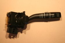
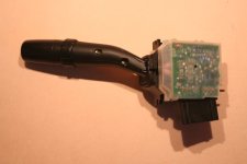
Took some pics of the switch in case you were wondering what you are looking to work with.

Front of the switch:
 

Attachments

  • t4rwwsw06.jpg
    t4rwwsw06.jpg
    51.3 KB · Views: 283
Last edited:
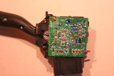
Closeup of the circuit board under the cover. Not sure how to dismantle it to get at the other side of the board so I didn't try.
 

Attachments

  • t4rwwsw08.jpg
    t4rwwsw08.jpg
    63.9 KB · Views: 294
Last edited:
Some of the components are visible on the bottom picture as surface mount resistors.
It looks like it's secured to the switch with solder posts. It will require a solder sucker to desolder the pins. Thanks for those pictures! Now we know what we are dealing with. It doesn't look hard to work on but you kind of have to wonder if you remove the board are springs going to shoot past your ear. :D
 

Members online

Forum statistics

Threads
278,310
Messages
3,554,076
Members
248,016
Latest member
Advally Service

Trending content

Back
Top