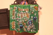
Wiper/washer switch mist mod

drmorbius said:
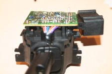
Some of the components are visible on the bottom picture as surface mount resistors.
It looks like it's secured to the switch with solder posts. It will require a solder sucker to desolder the pins. Thanks for those pictures! Now we know what we are dealing with. It doesn't look hard to work on but you kind of have to wonder if you remove the board are springs going to shoot past your ear. :D

There are all kinds of resistors, relays, etc., on the opposite side of the board. Removing the 2 screws pictured to the left of the board allows the switch to come apart to gain access but I think the circuit board will still be attached, as you said.
 
Kmvreter said:
There are all kinds of resistors, relays, etc., on the opposite side of the board. Removing the 2 screws pictured to the left of the board allows the switch to come apart to gain access but I think the circuit board will still be attached, as you said.

Any loose pieces after you took that apart or are you still able to put it back together easily? There should be only one relay, some semiconductors, resistors etc. Can you locate pin sixteen on the switch? From what I can see it might be labeled T16 on the board.
 
Last edited:
As I said earlier, I didn't actually take the switch apart. I have taken a sister (headlamp) switch apart in the past and had no difficulty putting it back together. I just took the washer switch out to take pics. Pin 16 can be located on connector C14 (black) using the connector schematic on page 386 of the wiring manual (this is the female connector on the harness.) This file is too big for me too attach at this time so I need to work on this.
 
Nothing better to do so I took the switch out again and this time I dismantled it. It isn't that difficult to pull apart and there aren't any springs flying around.
So, here is some more detail for the electronics wizzes willing to tackle this:

I'll start where I left off earlier.
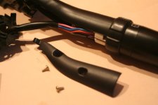
After removing the back plastic cover, remove the 2 screws. Then GENTLY pry back the tabs so the switch comes apart (shown partially apart in picture.)
 

Attachments

  • t4rwwsw09.jpg
    t4rwwsw09.jpg
    58 KB · Views: 263
Last edited:
Remove stalk cover plate using small (#0) Phillips screw driver. Small slider block will fall out when you pull the switch apart but don't worry about fitting it back in later (everything goes back together only one way; good TOY engineering.)
 

Attachments

  • t4rwwsw10.jpg
    t4rwwsw10.jpg
    56.7 KB · Views: 212
Last edited:
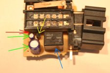
You now have access to the inside (top?) of the circuit board. In addition to the eletrical connectors, there are 5 electronic components on this side of the board.

Blue arrow is a relay.
Yellow arrow to an upright black semi-circular item (not sure what it is called.)
Green arrows to large and small items (I think these are capacitors.)
Red arrow to a resistor (hidden under the structure.)
 

Attachments

  • t4rwwsw11.jpg
    t4rwwsw11.jpg
    36.4 KB · Views: 212
Last edited:
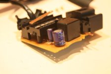
And another.

The markings on the purple (capacitors?) are:

Large diameter = 100uF 16V
Small diameter = 33uF 25V
I believe the large capacitor is for the front intermittent because Pin 16 shows continuity to one side of this item (the small capacitor is more than likely for the back window intermittent wiper.)

Not sure about the banding sequence on the resistor but they appear to be orange/black (or could be red/black.)
 

Attachments

  • t4rwwsw13.jpg
    t4rwwsw13.jpg
    22.9 KB · Views: 208
Last edited:
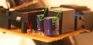
Finally, a closeup of the visible side of the circuit board. Now that I look at it, you can get to the connections to desolder them but things are very close together (tight fit.)
 

Attachments

  • t4rwwsw14.jpg
    t4rwwsw14.jpg
    84.8 KB · Views: 211
Last edited:
Sorry to chime in mid stream but that half circle black part is a transistor (yellow arrow). The big question is if the resistor is connected to both capacitors. If it is we will have to change the capacitor unless we also want to further delay the rear wiper at the same time.
 
Last edited:
Kmvreter said:
Finally, a closeup of the visible side of the circuit board. Now that I look at it, you can get to the connections to desolder them but things are very close together (tight fit.)

Ok I see a transistor on the solder side and a transistor on the other side. Do you have an ohmeter? If so you can measure that resistor with the bands on it if you aren't sure of the colors. It should connect to the other side of the larger of the two capacitors. It's an electrolytic cap and is also polarized so it only goes into the board one way. These things are cheap so you could go to Radio Shack and get a couple. You need to ask for a 47 or 50 microfarad 16 volt radial lead electrolytic capacitor and just remove the one on the board and replace it with the new one. Then reassemble and test the result. It would help to have a stopwatch to time the delay difference. I have to go out for awhile but will post again this evening.
 
I'm no expert at this so here goes:

drmorbius said:
... Do you have an ohmeter? YES

If so you can measure that resistor with the bands on it if you aren't sure of the colors. RESULT = 0.730 WITH THE METER SET AT THE RESISTOR FUNCTION. 0.011 WITH THE METER SET AT THE 2000M Ohm SCALE (DOES THAT MAKE SENSE?)

It should connect to the other side of the larger of the two capacitors. YES, I GET CONTINUITY BETWEEN THE RESISTOR AND THE ONE SIDE OF THE CAP. THE OTHER SIDE OF THE CAP IS WHERE I HAVE CONTINUITY TO PIN 16 ON THE CONNECTOR.

It's an electrolytic cap and is also polarized so it only goes into the board one way. These things are cheap so you could go to Radio Shack and get a couple. You need to ask for a 47 or 50 microfarad 16 volt radial lead electrolytic capacitor and just remove the one on the board and replace it with the new one. Then reassemble and test the result.
I UNDERSTAND REPLACING IT BUT THAT INVOLVES DESOLDERING AND SOLDERING. NOT MY FORTE. THE EXISTING PRONGS ARE BENT AND THEN SOLDERED.
ALSO, IS IT STRAIGHT MATH THAT THE 50uF CAP (HALF THE ORIGINAL 100uF) WILL DOUBLE THE INTERMITTENT SWEEP TIME? PLAYING WITH THE RC CIRCUIT LINK EARLIER IN THIS THREAD, SHOULDN'T WE BE INCREASING THE CAP (SAY TO 200uF) TO INCREASE THE DELAY?

It would help to have a stopwatch to time the delay difference. THIS ISN'T A PROBLEM

I'm definitely willing to give this a try but it's my daily driver. I need to reassemble it tonight, get the supplies and possibly try it later this weekend or week. The intimidating part is the desoldering in such close contact to other items on the board. Any tips on this would be appreciated.

ps. I also need to dig myself out from this snow storm and go make some tracks. Gotta love the T4R.
 
Last edited:
Kmvreter said:
I'm no expert at this so here goes:


I'm definitely willing to give this a try but it's my daily driver. I need to reassemble it tonight, get the supplies and possibly try it later this weekend or week. The intimidating part is the desoldering in such close contact to other items on the board. Any tips on this would be appreciated.

ps. I also need to dig myself out from this snow storm and go make some tracks. Gotta love the T4R.

Sorry I read it wrong yes it should be larger than 100 microfarads.

My favorite tool for this is called a solder sucker. It's just a tube with a small tip and a spring loaded piston. You hold the tip right up to the solder as you are making it molten with a small tipped soldering iron and as soon as it is molten you release the spring loaded piston and the molten solder is sucked into the tube. Don't spend for the metal pretty ones I like the 10'" plastic ones. About 5-7 $ US. Any way I can help I think you know by now I sure will try and I don't give up easily! If you happen to bridge between 2 traces on the board just let the solder get hard and then use the iron to wipe between the 2 traces. That will separate them again.
 
Last edited:
Thanks for the advice. I'll look for the solder sucker.
So, should I locate a 200uF cap? Does such an animal exist?
 
Wow, you guys are definitely making progress here....very nice.

Did you time the maximum delay of the switch before you start modifying the circuit?
 
Kmvreter said:
Thanks for the advice. I'll look for the solder sucker.
So, should I locate a 200uF cap? Does such an animal exist?

Yes but it will be larger in size and I'm starting to wonder how much space we have above that 100 mfd cap. We may have to take several smaller caps say a 100mfd/16v axial lead and add in parallel a 25mfd/16v. Axial lead caps have a wire coming out of each end of the body instead of the radial design thats in there now. This would allow us to make a cap that is not available "off the shelf". Caps add in parallel so you would hook the positives together on one side and the negatives together on the other, making a tight bundle. Then bring out one lead from each side(1 positive and 1 negative) and install this package on the board. In this way we could keep adding small caps until we achieve our goal. Does your ohmeter have a x1 scale? It sounds like that resistor is already pretty small. so our only choice is to go up in value on the cap.
 
If the large cap is for the front wiper delay, and the small cap is for the rear wiper delay, and both use the same resistor in their circuit, then would it be possible to time the wiper delay in front and in back and use math to determine how much delay a bigger cap will give us?

Does that make any sense?
 
Even Steven said:
If the large cap is for the front wiper delay, and the small cap is for the rear wiper delay, and both use the same resistor in their circuit, then would it be possible to time the wiper delay in front and in back and use math to determine how much delay a bigger cap will give us?

Does that make any sense?

To use the equation given earlier in this thread we need to know the value of the resistor. What Kmvreter is seeing is either 2 or 3 ohms depending on if the first band is red or orange. This isn't much more than just a piece of wire as far as resistance goes. I wish I could see the board in person but thats not an option right now. It almost seems as if they got the maximum delay possible with the space limitations and off the shelf parts since Toyota isn't going to take the time to make up a special capacitor and I can't blame them for that. Still it would have been nice if they had built the switch as it was advertised.
 
drmorbius said:
To use the equation given earlier in this thread we need to know the value of the resistor. What Kmvreter is seeing is either 2 or 3 ohms depending on if the first band is red or orange. This isn't much more than just a piece of wire as far as resistance goes. I wish I could see the board in person but thats not an option right now. It almost seems as if they got the maximum delay possible with the space limitations and off the shelf parts since Toyota isn't going to take the time to make up a special capacitor and I can't blame them for that. Still it would have been nice if they had built the switch as it was advertised.

I believe there are larger caps that are wider, but not taller. If you look at the pics, you can see that the two caps are the same height (or very close) and the big difference is in width.
 

Members online

Forum statistics

Threads
278,309
Messages
3,554,071
Members
248,016
Latest member
Advally Service

Trending content

Back
Top