Wiper/washer switch mist mod

Thanks for the update and the hard work. Based on the math the times don't match, so there must be something more to the circuit than just the RC part you are maniplating with these new caps. I wonder if there is a cap on the wiper motor? :confused:
 
Spider5 said:
Thanks for the update and the hard work. Based on the math the times don't match, so there must be something more to the circuit than just the RC part you are maniplating with these new caps. I wonder if there is a cap on the wiper motor? :confused:
There is still the resistor which has not been tried.
 
Spider5 said:
But the resistor was noted to be rather small (resistance).
Yes but I believe if you go up in resistance the delay gets longer according to the formula. Also at some point we will reach the point where nothing changes . Probably just doesn't fire at all. But lets see what happens without the 100ufd in the circuit.
 
Something else to consider:

How do we know for sure that hooking up different size caps in parallel is giving us accurate results? In other words, how do two different sized caps work together in parallel? Do we know for sure that removing the original cap and soldering in one of the larger caps will shorten the delay as compared with using them both together in parallel?
 
drmorbius said:
Yes but I believe if you go up in resistance the delay gets longer according to the formula. Also at some point we will reach the point where nothing changes . Probably just doesn't fire at all. But lets see what happens without the 100ufd in the circuit.

I fully agree, I was just looking at it from a mathematical perspective which Kmvreter had some frustrating comments about. With this in mind there appears to be a larger capacitance that would make the response time not linear with the increase in parallel capacitance being added. Often a capacitor is added to a cyclic motor to stablize the performance. If there is such a capacitor, and we know what size it is, we could have an easier time matching the time we are looking for with the capacitor selection for replacment, instead of the current trial and error method. That was my only reason for the initial comment.

As a side note; there could also be additional resistance somewhere in the circuit, but this would be less likely.

 
Spider5 said:
I fully agree, I was just looking at it from a mathematical perspective which Kmvreter had some frustrating comments about. With this in mind there appears to be a larger capacitance that would make the response time not linear with the increase in parallel capacitance being added. Often a capacitor is added to a cyclic motor to stablize the performance. If there is such a capacitor, and we know what size it is, we could have an easier time matching the time we are looking for with the capacitor selection for replacment, instead of the current trial and error method. That was my only reason for the initial comment.

As a side note; there could also be additional resistance somewhere in the circuit, but this would be less likely.
Yes , all true. I wish I could take my own out and experiment with it but it's just not in the cards right now. I wonder if it has something to do with the fact that the caps are bipolar, but I have reached my limit as I am not an engineer, just a very competent technician.
 
Last edited:
drmorbius said:
... but I have reached my limit as I am not an engineer, just a very competent technician.

Very competent indeed. I would like to start by thanking you for your assistance in identifying the BP cap situation and supplying the replacements.
Thanks to everyone for their insight and discussion.

How does 20/15/10/5 seconds sound. I call this mod a success.

To be more exact, after removing the existing cap and putting in the 470uF BP, I got the following:

Slow Med- Med+ Fast
Baseline: 8.5 6.9 4.6 3.0
Modded: 19.5 15.6 10.5 5.5

I'm not sure how the caps interacted while working with the temporary trial and error. The resistor discussion sounds good but you can't get at it easily to make changes there.

Please read on for the Plan D wiper switch capacitor mod.
 
Last edited:
Here's how to replace the 100uF capacitor to increase the wiper intermittent delay.
I'll start by saying this is not a mod for the faint of heart or lacking technical skill so be careful, have lots of patience and do this when you are in a good mood.

Start by getting the switch in your hands (refer to earlier posts.)
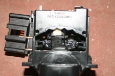
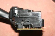
This picture is to point out, in this view of the switch, the orientation of the slide block mechanism that is activated by moving the stalk/lever. Look below the white pointer. This block will freely fall out when you open the switch body.
 

Attachments

  • t4rwwsw19.jpg
    t4rwwsw19.jpg
    80.5 KB · Views: 155
Last edited:
Remove the 2 brass screws and seperate the switch halves by prying the several tabs out of position. A trick I realized after doing this was you don't have to open the switch entirely. If you are good, just back off the 2 brass screws and slightly seperate the switch halves. This will save you from putting the lever pivot point back together and repositioning the slide block (which is tricky with the new big cap in place.)
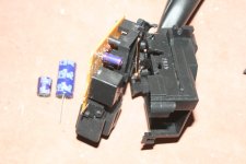
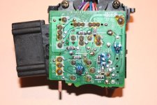
Here is a pic of the empty space after desoldering and removing the original cap (loose on the left to compare in size to the new.)
Desoldering seems intimidating at first but turns out to be relatively easy, especially with the right "sucker" tool.
 

Attachments

  • t4rwwsw20.jpg
    t4rwwsw20.jpg
    64.7 KB · Views: 152
Last edited:
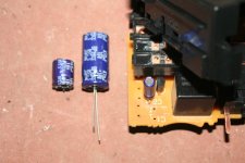
Another view with the cap removed (pulled the leads right out of the cap in the process of removing it.) Watch out not to damage the small cap when inserting the large cap because it will get bent and moved over.
 

Attachments

  • t4rwwsw21.jpg
    t4rwwsw21.jpg
    72 KB · Views: 153
Last edited:
Partially reassemble the switch, including the slide block, if you fully opened it earlier. Leave it slightly open. Partially reinsert brass screws.
 

Attachments

  • t4rwwsw22.jpg
    t4rwwsw22.jpg
    74.5 KB · Views: 154
Last edited:
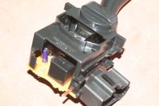
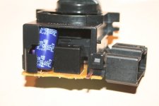
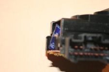
Insert the cap by pushing the leads through the holes in the circuit board. Then stuff the cap into place (you have to gently force it between the switch cover and the existing relay box.) Now close the switch halves together and tighten the screws. Push the cap into the switch so the body doesn't stick out. (This pic is after the soldering but you get the idea.)
 

Attachments

  • t4rwwsw26.jpg
    t4rwwsw26.jpg
    65 KB · Views: 165
Last edited:
Another view. You don't want the cap body outward because it will interfere with the final switch position in the steering column.
 

Attachments

  • t4rwwsw27.jpg
    t4rwwsw27.jpg
    38.6 KB · Views: 165
Last edited:
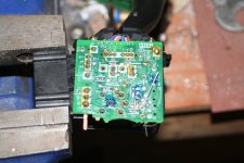
Held the switch in a vice to solder the leads. Don't trim them.
Try the switch in the vehicle in the temporary position by only hooking up the wiring connector. Don't insert it into the steering column. Turn it on and try it out. This is to see if it works and that you didn't screw anything else up with the soldering. (This is also the point you will notice the "extra" mystery feature I'll reveal at the end of the write-up.) Also, be careful not to touch the circuit board when the switch is live.
 

Attachments

  • t4rwwsw24.jpg
    t4rwwsw24.jpg
    96.3 KB · Views: 173
Last edited:
Remove the switch and trim the leads. Not a pretty job on the first one (burnt) but it works.
Reassemble the protective cover over the circuit board, put it back in it's home on the vehicle and finally put the steering trim back together.
 

Attachments

  • t4rwwsw25.jpg
    t4rwwsw25.jpg
    98.5 KB · Views: 166
Last edited:
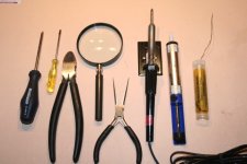
Finally, the many tools required, especially the "solder sucker" and the magnifying glass (the "progressive lenses" aren't enough in this case.)

The mystery bonus feature is a double swipe when you first activate the intermittent wipe. I believe this is due to the size of the cap and the amount of stored energy being released. I don't mind this feature right now and I'll see if I get used to it.

This concludes the Plan D method of this mod. I still have my Plan C washer disable switch. I'll hide it in behind the driver's side fuse box cover and use it as a seasonal thing (I never use washer fluid in the 3 seasons.)

Enjoy the ride!
 

Attachments

  • t4rwwsw28.jpg
    t4rwwsw28.jpg
    67.3 KB · Views: 159
Last edited:
Thanks for the excellent write-up. Two questions:

What are your final delay times?

Were you getting a double swipe when you had both caps in parallel?

Sometimes I get a double swipe when I hit my front washers. The wipers will do two passes and then return to the off position. Other times I only get a single swipe. I'm not sure why it happens, but it does...

Do you get the double swipe every time you switch to intermittent wipe?
 

Members online

Forum statistics

Threads
278,310
Messages
3,554,077
Members
248,016
Latest member
Advally Service

Trending content

Back
Top