
Carl Fisher
New member
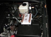
Prototyping power distribution for future power hungry upgrades plus the standard big 3 upgrade and the audio amp run. I'm not happy with the layout yet but it at least shows some of the ideas I'm playing around with. Ultimately there will be a plexi cover over the entire assembly.
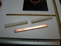
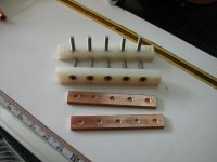
This shows the home made bus bars from 3/16" x 3/4" copper, UHMW and 1/4x20 stainless hardware. There will be a 1/0awg feed to each side of the bus from the battery and then branch off as needed with Pico copper rings.
My only unknown is if I want to fuse between the battery and the bus bar. If I do decide to fuse between the two, I may relocate the entire assembly to the passenger side of the engine compartment in the big empty space over the wheel well.
Once I finalize the layout, I'll make a permanent base painted red and black to distinguish the two sides.
Comments and ideas welcome.
This shows the home made bus bars from 3/16" x 3/4" copper, UHMW and 1/4x20 stainless hardware. There will be a 1/0awg feed to each side of the bus from the battery and then branch off as needed with Pico copper rings.
My only unknown is if I want to fuse between the battery and the bus bar. If I do decide to fuse between the two, I may relocate the entire assembly to the passenger side of the engine compartment in the big empty space over the wheel well.
Once I finalize the layout, I'll make a permanent base painted red and black to distinguish the two sides.
Comments and ideas welcome.
Attachments
Last edited:


