so before we go any further here, my field of study is manufacturing engineering, not mechanical, so any advice in that regard is greatly appreciated. I have been using inventor for more than 6 years and solidworks for about 5 years, mostly for modeling on various projects. I dont know all that much about stress analysis so you will have to bear with me here until I do a bit more research. what im saying is feel free to school me on it as im just figuring it out as I go. also dont hold your breath i have a very busy schedule this semester.
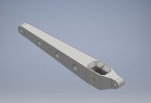
I redid the entire arm to the length it will be eventually which is 30", it has two backbones running through and has an outer shell as well, all in 3/16 mild steel. the strength of the first arm was being held back because what I already had there was limiting the design. this one worked out a lot better.
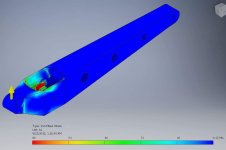
for the fea setup, I constrained the frame end of the link as a pin, and im planning on making a platform that will be conected to the shock mount. the platform will be constrained to a frictionless plain in order to allow it to move. perhaps the proper way to set it up would be to make a frame and connect the shock and end of the link to it so it can move the way its supposed to.
Im not sure if I mentioned this, but the upper shock mount will also move up about 5" and there is plenty of room for it, then ill cut a couple access holes in the cab and seal them with small deckplates.
also did you ever find any evidence that the rigidity modulus was different for different typesband tempers of spring steel? all of the information i found pointed towards them.being all about the same.