D Farms' Build thread: "Goldilocks"

I think what [MENTION=56756]1985taylor1925[/MENTION] is saying is that with the stock mounts the shock is angled forward which will give you an efficiency knock down as well. You want your shocks moving towards parallel with the direction of motion so they'll get "more efficient" as the suspension compresses (assuming you want that, that would be the same thing as progressive valving but from a geometry perspective). If the shock is angled forward to begin with it'll rotate forward as the axle bumps which will make it act softer as you compress more.

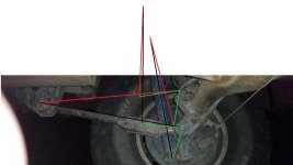
forgive my crude drawing here, but its about the same. also since both shocks move in, it should give more flex travel, as if I needed it.
 

Attachments

  • shock compression.jpg
    shock compression.jpg
    101.5 KB · Views: 877
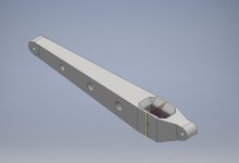
screw ill just do a whole new arm from scratch, 30" and call it a day.
 

Attachments

  • beef arm.jpg
    beef arm.jpg
    39.3 KB · Views: 855
As i mentioned before im always working on the grille, my latest mod is to get rid of the oval toyota symbol, and continue the profile of the grille all the way across, and then of course color match it. if it looks good i might even stick the old block letter style toyota emblem on it. I 3d printed the piece that covers up the old oval and continues the contour of the grill. I think it will probably look best without the toyota block letters but we will see.
66.gif
 
Last edited:
forgive my crude drawing here, but its about the same. also since both shocks move in, it should give more flex travel, as if I needed it.

That's the geometry I was trying to visualize. I guess the angle isn't nearly as extreme as what I had imagined. I'm interested in seeing how much the shocks will be softened by the new geometry. But, out of curiosity, why not just find a different shock that is about the same length as the lc shocks but valves a little softer?
 
That's the geometry I was trying to visualize. I guess the angle isn't nearly as extreme as what I had imagined. I'm interested in seeing how much the shocks will be softened by the new geometry. But, out of curiosity, why not just find a different shock that is about the same length as the lc shocks but valves a little softer?

more travel.
 
subbed i have a feeling this geometry isnt going to work. I would just not waste your time and get longer shocks. Also dont trust that FEA, do the hand calculations, dynamic not static...


also travel is usually a function of shock length in a proper setup.

[MENTION=57546]4-Ripcord[/MENTION] [MENTION=50828]turbodudey2[/MENTION]
 
Last edited:
more travel.

You said that for 9" of travel at the shock you will get 12" of travel at the axle . . . is that a calculated number?

And then, looking at the picture, just by mounted the shock at that location on the lca, you will be compressing it a good 4" or 5" inches (just a estimate from looking at the picture), unless of course you raise the location of the upper shock mount locations at the frame. So you will be reducing the shock travel proportionally by that amount right off the bat. The shocks will also be in a stiffer region of the valving with being compressed. Arent you concerned about that offsetting the goal of softening the shock?
 
subbed i have a feeling this geometry isnt going to work. I would just not waste your time and get longer shocks. Also dont trust that FEA, do the hand calculations, dynamic not static...


also travel is usually a function of shock length in a proper setup.

[MENTION=57546]4-Ripcord[/MENTION] [MENTION=50828]turbodudey2[/MENTION]

so before we go any further here, my field of study is manufacturing engineering, not mechanical, so any advice in that regard is greatly appreciated. I have been using inventor for more than 6 years and solidworks for about 5 years, mostly for modeling on various projects. I dont know all that much about stress analysis so you will have to bear with me here until I do a bit more research. what im saying is feel free to school me on it as im just figuring it out as I go. also dont hold your breath i have a very busy schedule this semester.

I redid the entire arm to the length it will be eventually which is 30", it has two backbones running through and has an outer shell as well, all in 3/16 mild steel. the strength of the first arm was being held back because what I already had there was limiting the design. this one worked out a lot better.

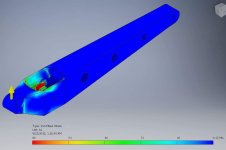
for the fea setup, I constrained the frame end of the link as a pin, and im planning on making a platform that will be conected to the shock mount. the platform will be constrained to a frictionless plain in order to allow it to move. perhaps the proper way to set it up would be to make a frame and connect the shock and end of the link to it so it can move the way its supposed to.

Im not sure if I mentioned this, but the upper shock mount will also move up about 5" and there is plenty of room for it, then ill cut a couple access holes in the cab and seal them with small deckplates.

also did you ever find any evidence that the rigidity modulus was different for different typesband tempers of spring steel? all of the information i found pointed towards them.being all about the same.

 
Last edited:
You said that for 9" of travel at the shock you will get 12" of travel at the axle . . . is that a calculated number?

And then, looking at the picture, just by mounted the shock at that location on the lca, you will be compressing it a good 4" or 5" inches (just a estimate from looking at the picture), unless of course you raise the location of the upper shock mount locations at the frame. So you will be reducing the shock travel proportionally by that amount right off the bat. The shocks will also be in a stiffer region of the valving with being compressed. Arent you concerned about that offsetting the goal of softening the shock?

moving the shock mount up, also I dont have bypass shocks.

yes its calculated, but that was with the stock arm length, I moved the shock foreward on the arm 5.25" and the arm is 21" long hence 15.75:21=9:12
 
Last edited:
Shock damping forces

It looks like the stress analysis for the lower control arm is a bit off. I believe you have erred on the conservative side though, so the end product will probably be way overbuilt. (which may not be a bad idea anyway)

But here's where we went wrong: The compression and rebound damping forces the shock will exert are solely a function of the shock shaft velocity. You may be able to find a shock dyno graph from the manufacturer, but if not, the forces on the lower control arms will be purely guesswork. Plus, even if you did come up with the shock dyno info, you would still have to guess at the shaft velocity.

If I was to venture a guess, I would say the shock damping forces are on the order of 300 - 500 lbf. (about 10x less than what you were using in your model)

The geometry you proposed looks like it should work. You'll just want to make sure you don't end up under-damping the rear axle.
 
It looks like the stress analysis for the lower control arm is a bit off. I believe you have erred on the conservative side though, so the end product will probably be way overbuilt. (which may not be a bad idea anyway)

But here's where we went wrong: The compression and rebound damping forces the shock will exert are solely a function of the shock shaft velocity. You may be able to find a shock dyno graph from the manufacturer, but if not, the forces on the lower control arms will be purely guesswork. Plus, even if you did come up with the shock dyno info, you would still have to guess at the shaft velocity.

If I was to venture a guess, I would say the shock damping forces are on the order of 300 - 500 lbf. (about 10x less than what you were using in your model)

The geometry you proposed looks like it should work. You'll just want to make sure you don't end up under-damping the rear axle.

snivilous and I had a conversation about this, basically this would be the worst case scenario, like driving accross the desert at 75mph and doing a 4ft jump without springs and a solid beam instead of a shock. snivilous recommended using a force of 10g only the corner weight, which in the back is about 10000lb maybe a bit less. anyways after adjusting the fea a bit more heres the new arm at 20,000lb of force, most of the stress is around the shock mount itself, ill increase the diameter of the bolt to fix that problem.
 

Attachments

  • received_1050557724968271.jpeg
    received_1050557724968271.jpeg
    34 KB · Views: 802
snivilous and I had a conversation about this, basically this would be the worst case scenario, like driving accross the desert at 75mph and doing a 4ft jump without springs and a solid beam instead of a shock. snivilous recommended using a force of 10g only the corner weight, which in the back is about 10000lb maybe a bit less. anyways after adjusting the fea a bit more heres the new arm at 20,000lb of force, most of the stress is around the shock mount itself, ill increase the diameter of the bolt to fix that problem.

That's cool. It does seems a bit extreme, since the max force will likely be in the 500 lbf range. Vehicle weight also has very little affect on the damping force since it's the unsprung weight that will primarily affect the rebound velocity of the shock.
 
That's cool. It does seems a bit extreme, since the max force will likely be in the 500 lbf range. Vehicle weight also has very little affect on the damping force since it's the unsprung weight that will primarily affect the rebound velocity of the shock.

I think you are dead on, if you look here this icon shock shows about 1300lbf for the front I believe. anyways thats why im going to test my short links first, they can definitely stand up to 500lb of force.
https://www.tacomaworld.com/threads...-damping-control-valve-upgrade-option.276901/
 
moving the shock mount up, also I dont have bypass shocks.

yes its calculated, but that was with the stock arm length, I moved the shock foreward on the arm 5.25" and the arm is 21" long hence 15.75:21=9:12

That makes sense. I suspect that the actual suspension "feel" you end up with is quite unpredictable despite the math, due to the many variables involved. But I will be really interested in hearing your conclusions when its finished. I love anything suspension related, especially when its custom and unique. Cool project!
 
so before we go any further here, my field of study is manufacturing engineering, not mechanical, so any advice in that regard is greatly appreciated. I have been using inventor for more than 6 years and solidworks for about 5 years, mostly for modeling on various projects. I dont know all that much about stress analysis so you will have to bear with me here until I do a bit more research. what im saying is feel free to school me on it as im just figuring it out as I go. also dont hold your breath i have a very busy schedule this semester.

I redid the entire arm to the length it will be eventually which is 30", it has two backbones running through and has an outer shell as well, all in 3/16 mild steel. the strength of the first arm was being held back because what I already had there was limiting the design. this one worked out a lot better.

for the fea setup, I constrained the frame end of the link as a pin, and im planning on making a platform that will be conected to the shock mount. the platform will be constrained to a frictionless plain in order to allow it to move. perhaps the proper way to set it up would be to make a frame and connect the shock and end of the link to it so it can move the way its supposed to.

Im not sure if I mentioned this, but the upper shock mount will also move up about 5" and there is plenty of room for it, then ill cut a couple access holes in the cab and seal them with small deckplates.

also did you ever find any evidence that the rigidity modulus was different for different typesband tempers of spring steel? all of the information i found pointed towards them.being all about the same.

I apprecaite that you didn't take the criticism poorly. I have a super busy semester as well, and don't have time or the expertise yet to comment on the actuall suspension geometry, thus calling in Turbo, and 4Rip.

I guess my main question is why? A 4 link setup like ours is a pretty proven design and if you are really concerned about travel why not just get longer shocks? It just seems like a lot less work, and it takes all the guess work and work work out of it lol.

As for the spring steel deal I didn't do any research on it, I had meant to, but at this point I can't even remember what it pertained to lol.
 
If I was to venture a guess, I would say the shock damping forces are on the order of 300 - 500 lbf. (about 10x less than what you were using in your model)

Yep I agree there, my concern was the stress concentrations from the other forces on the bar.

The geometry you proposed looks like it should work. You'll just want to make sure you don't end up under-damping the rear axle.

This is a good point as well.
 
To get more travel out of the rear, you cant just put longer shocks without having them in the cab. by mounting the shock on the arm, you can get a lot more travel. im planning on 3 linking it similar to what 4running daily showed it in his thread. the longer arms will also give it smoother travel and be more controllable at speed. it will also have less roll steer than the factory short link setup. the gas tank is in the way of moving the upper arms forward, so a 3 link is the only option for longer arms without moving the tank. It will also be good experience, since at some point i want to do an solid axle on the front. at this point all of my links are shot in the back, so its either buy some new ones from toyota, buy some aftermarket ones, or make my own.

Also I have to do something with the locked axle sitting in my garage haha.
 
Last edited:
To get more travel out of the rear, you cant just put longer shocks without having them in the cab. by mounting the shock on the arm, you can get a lot more travel. im planning on 3 linking it similar to what 4running daily showed it in his thread. the longer arms will also give it smoother travel and be more controllable at speed. it will also have less roll steer than the factory short link setup. the gas tank is in the way of moving the upper arms forward, so a 3 link is the only option for longer arms without moving the tank. It will also be good experience, since at some point i want to do an solid axle on the front. at this point all of my links are shot in the back, so its either buy some new ones from toyota, buy some aftermarket ones, or make my own.

Also I have to do something with the locked axle sitting in my garage haha.

You will have more droop, but you loose all your up travel... That is if you are planning on running your 'stock' LC shocks, If not you don't really gain anything. I understand the concept, but it is just a pain, because you will have to end up changing valving to make it ride/handle right.
 
Last edited:
i think you missed the part where I moved the upper shock mount upwards. the tokico shocks are valved for 5000lbs, the shock orientation in the landcruiser is angled outwards, my shocks will be nearly verticle. on the 30" arm the motion ratio will only be 1:1.25 so I will get roughly 11.25" of travel. the damping will also be less, infact it will be perfect for a vehicle that weighs 4000lbs if the shocks were angled outward, but they are straight and will be more efficient.

Everything you wanted to know about Shock Absorbers - 4x4Review Off Road Magazine

anyways it all works out.
 
i think you missed the part where I moved the upper shock mount upwards. the tokico shocks are valved for 5000lbs, the shock orientation in the landcruiser is angled outwards, my shocks will be nearly verticle. on the 30" arm the motion ratio will only be 1:1.25 so I will get roughly 11.25" of travel. the damping will also be less, infact it will be perfect for a vehicle that weighs 4000lbs if the shocks were angled outward, but they are straight and will be more efficient.

Everything you wanted to know about Shock Absorbers - 4x4Review Off Road Magazine

anyways it all works out.

I did see that, but I don't understand where you plan on moving it to I guess. Thanks for the article I have read it before though. I am not sure what your gross weight is, but I had mine on the scale recently and I was sitting at 4750lbs with an 60-30 weight distribution aprox.
 

Members online

Forum statistics

Threads
278,315
Messages
3,554,102
Members
248,016
Latest member
Advally Service

Trending content

Back
Top