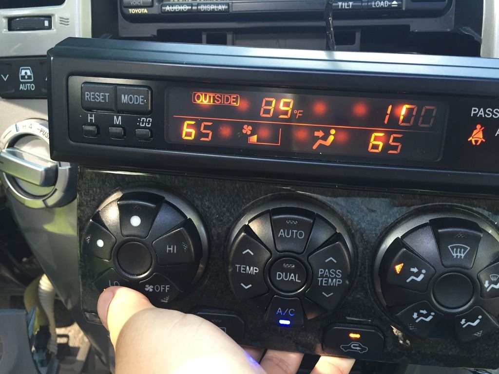
This is not a great picture but I changed the yellow inverter on indicator to blue. This requires a small piece of 1/8" thick transparent plexiglass that has to be cut and shaped to fit like the yellow piece the switch comes with.
This is a project that I have been working on for a while now. First and foremost, I want to give a big shout out to my buddy Bill for helping me out by cutting a few pieces on his CNC mill and coming up with a better idea than what I had in mind.
A few months ago I replaced my factory head unit with a single din unit so that I could have a bluetooth connection while driving. One thing that kind of irritated me about the single din adapter is the goofy pocket right below the radio. Here is what I came up with to make things look a lot better.
When I have time, I'll try to get some more pictures posted up showing how this was done. Let me know what you think.
That pocket is for your iphone. Looks great!
I see a lot of people scab bing the neo3 connectors to put in a led. Did y'all know the make neo3 LEDs. Totally want to do this but the wife get jealous when I spend to much time with the "mistress" as she has named her.
I picked up my 04 Sport Edition last week and drove it almost 21 hours straight from PA to TX. During that time, quickly noticed that half of the LCD was dim (the more important half on this trip, the clock, I was hauling ass and didn't need to be constantly reminded of my MPG at 3am). A few searches on the forum and I found the solution, but just to check, I popped the control panel off and swapped the L & R bulbs and sure enough the dim side switched. Thank you search button and T4R...
But that piqued my curiosity. This is a picture of my current display
I've searched and seen that some members have this issue, some don't. What I am looking at is the temp arrows going up and down not being lit. Actually, my entire center knob doesn't have any lighting except the left and right arrows. I had to get to work, so I didn't play swap-around with the knobs, but I am sure they need new bulbs for backlighting. Soldering isn't my forte, and if that's the answer then I won't really pursue this much more. But my question is...is there any outward physical appearance that would indicate the LED soldered to the board is bad? Is it just a coincidence that both the up and down arrows are out as opposed to an up/left or up/right combination?
I've already put in an order for an assortment of LEDs. They're cheap and the NEO bulbs are easy to swap in and out. My other question is do the superbrightleds.com bulbs require sanding in order to fit? I saw some posts saying yes, I saw others saying it's plug and play. Not an issue if they do, but I don't want to plan around a job being quick and easy if it is actually more involved.
you should have backlight on your center knob, just a matter of replacing the bulb there
The up/down arrow do NOT have LEDs behind them, so perfectly normal there. no real way to tell if an LED is bad just by looking at it. here is a pic of the actual board (notice the LEDs on either side, but not on the top/bottom. that LED on the lower left is the backlight bulb)...
i have never had to sand down any LED on the swaps I have done. They are a tighter fit, but pop right in.
This is a project that I have been working on for a while now. First and foremost, I want to give a big shout out to my buddy Bill for helping me out by cutting a few pieces on his CNC mill and coming up with a better idea than what I had in mind.
A few months ago I replaced my factory head unit with a single din unit so that I could have a bluetooth connection while driving. One thing that kind of irritated me about the single din adapter is the goofy pocket right below the radio. Here is what I came up with to make things look a lot better.
When I have time, I'll try to get some more pictures posted up showing how this was done. Let me know what you think.
Well the LEDs came today and I gotta say that was about as easy of a job as I've ever done and I'm 100% satisfied and possibly addicted to changing all of the lighting now...
Before
After
I swapped the rear window light as well because I had some bulbs left over. I couldn't figure out how to get to the 4x4 selector light, so that will have to wait. Also changed all of the door sill lighting but didn't get a photo of them.
Well the LEDs came today and I gotta say that was about as easy of a job as I've ever done and I'm 100% satisfied and possibly addicted to changing all of the lighting now...
Before
After
I swapped the rear window light as well because I had some bulbs left over. I couldn't figure out how to get to the 4x4 selector light, so that will have to wait. Also changed all of the door sill lighting but didn't get a photo of them.
Where did you get your lights? I bought some a few months back for the info center display. They were bright as I was plugging in the harness but soon as it clicked and locked they instantly went dim. and couldnt be seen through the display. the ones for my mode and reset worked great but the screen not so much. I ended up buying the stock bulbs from toyota and they worked fine, though I dont really care for that color.
[MENTION=30225]yosh2000[/MENTION]
I bought the neo4s last time but they were the hp's. I looked at your links but nothing going to superbright leds, they were all to led lighthouse. is there a reason the hp's wouldnt work vs the standards?
[MENTION=30225]yosh2000[/MENTION]
I bought the neo4s last time but they were the hp's. I looked at your links but nothing going to superbright leds, they were all to led lighthouse. is there a reason the hp's wouldnt work vs the standards?
of course the HPs work with the 12v mod, youre giving them the 12v they need. but with a standard PnP approach, which most everyone on here does, it doesnt.
some guys have a hard enough time getting polarity correct, why post that and complicate things?! why not post a link to a DIY on the 12v mod for people searching this thread in your previous post to help guys out if they want to go that route.
Hahahahaah. JK Alex, (one bulb wasnt getting juice, couldnt tell if connection was good or bad when I disaected it).
[MENTION=30225]yosh2000[/MENTION] : All I know is that he got the positive from the HVAC harness and respected the negative terminals of the base. (Does that make sense?)
yep, its just a matter of finding a 12v source and ensuring the LED gets its power from that and not the 6v on the board. simple, but again, yet another thing that can cause guys issues if they dont know what they are doing.
yep, its just a matter of finding a 12v source and ensuring the LED gets its power from that and not the 6v on the board. simple, but again, yet another thing that can cause guys issues if they dont know what they are doing.