
You are using an out of date browser. It may not display this or other websites correctly.
You should upgrade or use an alternative browser.
You should upgrade or use an alternative browser.
Extreme 3rd Gen Build! Insane!
- Thread starter NotKewl
- Start date

NotKewl
New member
hone:
:juggle:
I've been in Texas all week on business. Just got back last night and am in the shop today and all weekend. Got a lot of work to do to catch up. Just ordered all the wiring supplies I need to get that started too. That comes in on Sunday.

eatpasta
New member
I've been in Texas all week on business. Just got back last night and am in the shop today and all weekend. Got a lot of work to do to catch up. Just ordered all the wiring supplies I need to get that started too. That comes in on Sunday.
:whip2:
enough work! now back to work!
:becky:
heh - I love seein this stuff. A project with no limitations realized to it's potential!
It's a thing of beauty.

NotKewl
New member
Today I start my favorite part, the electrical wiring! :jaw:
I know right, he must be being sarcastic, WIRING, that's so tedious. Yes, it is, but I love it. I build my own RC components for the scratch built planes and drones I build (well when I'm not spending all my time doing this) and I love planning electrical circuits and systems. Pics will come later tonight.
I know right, he must be being sarcastic, WIRING, that's so tedious. Yes, it is, but I love it. I build my own RC components for the scratch built planes and drones I build (well when I'm not spending all my time doing this) and I love planning electrical circuits and systems. Pics will come later tonight.
NotKewl
New member
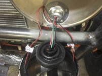
So this is pretty much ALL I got done today. Mostly because I am ANAL RETENTIVE about good wiring. I ran the wires to the fuel pump and tank sending unit. Yup, that's it! They are tucked away nice and neat. Good crimped and soldered connections, neatly heat wrapped and taped, and all properly grounded and fused!
I always start with a good schematic I draw up of each circuit.
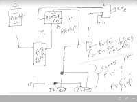
Why use a relay you ask? Well, you'd be stupid not to. You want power going to the device (Fan, Pump, Lights, etc.) not, through the switch. The relay takes the bulk of the power (using thicker gauge wires) and the switch just has enough power to flip the relay on. Keeps your stuff from heating up and catching fire! And ALWAYS go through a fuse. Inline or a block. I'm using a secondary block with blade fuses.
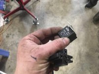
If you looked at the schematic I drew, you may be wondering what switched power is. Well, it's exactly what it sounds like. The power from the ignition switch. If you are wondering where that is on a 3rd gen T4R, it's the black wire with yellow stripe.
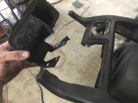
i cut out the ash tray and 12v plugs.
Made some templates using foam board.
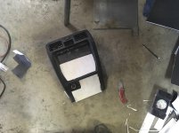
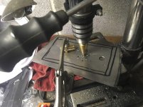
Cut and drilled the sheet metal. 16ga.
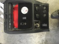
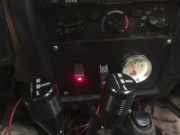
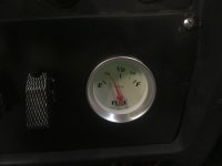
Painted them up and installed all the switches. The two switches by the fuel gauge are for the fuel pump and cooling fan. The lower carbon switch is for the rear line lock and the rest are for rock lights and light bar. Yes, I could run the fuel pump to the ignition switch, but I'd rather have a separate fused switch for safety reasons. Easier to just kill the fuel with a switch.
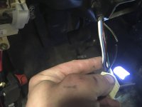
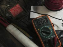
I always test each circuit after I wire it up just to make sure it works correctly. This is testing the ignition switch power lead. Good to go!
I always start with a good schematic I draw up of each circuit.
Why use a relay you ask? Well, you'd be stupid not to. You want power going to the device (Fan, Pump, Lights, etc.) not, through the switch. The relay takes the bulk of the power (using thicker gauge wires) and the switch just has enough power to flip the relay on. Keeps your stuff from heating up and catching fire! And ALWAYS go through a fuse. Inline or a block. I'm using a secondary block with blade fuses.
If you looked at the schematic I drew, you may be wondering what switched power is. Well, it's exactly what it sounds like. The power from the ignition switch. If you are wondering where that is on a 3rd gen T4R, it's the black wire with yellow stripe.
i cut out the ash tray and 12v plugs.
Made some templates using foam board.
Cut and drilled the sheet metal. 16ga.
Painted them up and installed all the switches. The two switches by the fuel gauge are for the fuel pump and cooling fan. The lower carbon switch is for the rear line lock and the rest are for rock lights and light bar. Yes, I could run the fuel pump to the ignition switch, but I'd rather have a separate fused switch for safety reasons. Easier to just kill the fuel with a switch.
I always test each circuit after I wire it up just to make sure it works correctly. This is testing the ignition switch power lead. Good to go!
Attachments








Last edited:
eatpasta
New member
Wiring and electronics is my personal biggest failing.
I grew up doing R/C stuff also and had my own pretty badass soldering station by the time I was in 4th grade but actually understanding circuits, I do not. At all.
None of the gauges in my CJ7 work. I spent half an hour yesterday trouble shooting all the wiring under the hood and just gave up after just fiddling around for about 28 minutes
:wacko:
I grew up doing R/C stuff also and had my own pretty badass soldering station by the time I was in 4th grade but actually understanding circuits, I do not. At all.
None of the gauges in my CJ7 work. I spent half an hour yesterday trouble shooting all the wiring under the hood and just gave up after just fiddling around for about 28 minutes
:wacko:
NotKewl
New member
Wiring and electronics is my personal biggest failing.
I grew up doing R/C stuff also and had my own pretty badass soldering station by the time I was in 4th grade but actually understanding circuits, I do not. At all.
None of the gauges in my CJ7 work. I spent half an hour yesterday trouble shooting all the wiring under the hood and just gave up after just fiddling around for about 28 minutes
:wacko:
My CJ7 was like that. Constantly chasing down wiring grimlins. Do yourself a favor and just get a complete new harness from painless performance for the CJ's it's easily installed by an amateur over a weekend and will make everything (that's not itself broken) work again. It's priced well too and just a few hundred bucks for the COMPLETE chassis kit.
eatpasta
New member
My CJ7 was like that. Constantly chasing down wiring grimlins. Do yourself a favor and just get a complete new harness from painless performance for the CJ's it's easily installed by an amateur over a weekend and will make everything (that's not itself broken) work again. It's priced well too and just a few hundred bucks for the COMPLETE chassis kit.
You'd probably have a heart attack if you saw under the hood on my Jeep.
1983, so early Smog engine with wires and hoses all over, mystery end of wires just dangling here and there, valve cover leak, rear main seal leak, oil pressure sender leak, just coming off of 10 years of storage and ~20 years of differed maintenance from a kid that got it as his first car that's just now able to get started making everything right...so I can (mostly) only blame myself.
:noidea:
My dad never forced me to sit and learn how to work on it and I didnt care because I was 15.
I have almost enough saved for Fuel injection, next will be rear axle upgrade and locker. Maybe after that will be new wiring harness...

MN4runnerman
Senior Member
You'd probably have a heart attack if you saw under the hood on my Jeep.
1983, so early Smog engine with wires and hoses all over, mystery end of wires just dangling here and there, valve cover leak, rear main seal leak, oil pressure sender leak, just coming off of 10 years of storage and ~20 years of differed maintenance from a kid that got it as his first car that's just now able to get started making everything right...so I can (mostly) only blame myself.
Wow you described my jeep to a T when I first bought it. I've cleaned most of it up over the years but there are still things that don't work right and it's the wiring to blame. The PO was a backwoods kind of guy where if it was broke he halfassed it when fixing.
NotKewl
New member
Wow you described my jeep to a T when I first bought it. I've cleaned most of it up over the years but there are still things that don't work right and it's the wiring to blame. The PO was a backwoods kind of guy where if it was broke he halfassed it when fixing.
I've owned a few cars from POs like that! Made me sad and angry at same time with some of them.
eatpasta
New member
I've owned a few cars from POs like that! Made me sad and angry at same time with some of them.
Mine is a salvage because the original owner burned up the engine (literally) and they put a new one in it but the guy never came back for it. So they salvaged it and friends of our family bought it and we bought it from them.
I don't think the garage that replaced the motor really knew what they were doing...
Im in the slow process of making it right but it may take the course of my natural life. Getting anything done with kids is a tiny miracle, Im sure as Kewl KNOWS!
:focus:
NotKewl
New member
Mine is a salvage because the original owner burned up the engine (literally) and they put a new one in it but the guy never came back for it. So they salvaged it and friends of our family bought it and we bought it from them.
I don't think the garage that replaced the motor really knew what they were doing...
Im in the slow process of making it right but it may take the course of my natural life. Getting anything done with kids is a tiny miracle, Im sure as Kewl KNOWS!
:focus:
For REAL! Kids do have a way of tying you down :ballchain:
To do this kind of stuff also takes a good woman who understands the need to tinker in a manly garage doing manly things. Not one who says things like, "You spend more time with those damn cars than me!" Well yeah, those cars make me happy and they don't complain when I'm not around! :heh:
But I digress. Now... :focus:
eatpasta
New member
For REAL! Kids do have a way of tying you down :ballchain:
To do this kind of stuff also takes a good woman who understands the need to tinker in a manly garage doing manly things. Not one who says things like, "You spend more time with those damn cars than me!" Well yeah, those cars make me happy and they don't complain when I'm not around! :heh:
But I digress. Now... :focus:
hahaha - yeah. Unfortunately, I have the Jeep that takes lots of time...and a bunch of motorcycles and the racing, then guitars, surfing, photography etc etc
Now that I think about it, it's kind of amazing that I even got married. Wife is pretty awesome for sure
NotKewl
New member
Got a couple of PM requests to explain the wiring in a little more detail, which I don't mind at all.
Let's get one thing clear. Stock wiring for use on ANYTHING that doesn't come from the factory is a very bad idea. The wire was chosen to work with a particular load over a specific distance (that's what us engineers do, calculate shit like that). If you introduce a new device (aftermarket cooling fan, more powerful lights, stereo system, etc.) You need to re-engineer the circuit to handle the specified load. You may also need a more powerful battery (or dual batteries) and upgraded charging system (as is the case with powerful stereos).
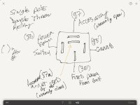
All my new circuits use a 30-40 amp rated Single Pole Double Throw (SPDT) relays. That means that two pins get accessory power when tripped. One at a time, though. One (pin 87) is normally open so only when tripped does it get power. The other (pin 87a, which I don't use) is normally closed, which means it has power all the time when the relay is not tripped. When you trip the relay 87a loses power. Most cars use a Single Pole Single Throw relay on just about every accessory circuit. Headlights, Brake Lights, Interior lights, Wipers, Fans, Fuel Pumps, etc. Anything that takes a load (measured in Amperes). The relay takes the load so the switch does not have to, preventing the switch from heating up (and potentially burning out or worse causing a FIRE!)
Here is a simple diagram of how an SPDT relay is wired up. For an SPST relay there is no
pin 87a. 4 pins instead of 5, so they are both easy to identify.
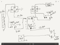
This is a diagram of two circuits running through a common fuse block. I will use 12 Gauge wire for the relay power and switched power due to amp draw and the switches only need 16 AWG wire. Well, 18 AWG. would work, but I prefer to go bigger than the math says when you are close to a threshold. Smaller the wire, the more resistance (Ohms) which means higher voltage drops. It also means the wire can become the fuse, which you don't want. That = Fire!
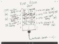
A detail drawing of the fuse block plan and the calculated amp fuse size for each block.
So how do you know what size fuse to use and how big wire you need for each circuit? Well, let's first look at the basic units of measure in Electricity.
Voltage, Amperes, Watts, and Ohms.
V = Volts (Voltage, think of it as pressure to make it easier to understand later) That's our constant for most vehicles (12 Volts).
I = Amps (This measures Current)
r = Ohms (This measures resistance)
W = Watts (Power output).
So what we are solving for is the current draw (amps) to determine which fuse size and wire size we need.
Most things like cooling fans, fuel pumps, wiper motors, etc. measure draw in amps, so it's easy to figure out. But lights are measured in watts meaning you need to do a little math. Let's take my Rock Lights as an example. They are 18 Watt lights each and since I am running 4 lights front (one circuit) and 4 out back (a separate circuit). 4 x 18 = 72 watts total power required on a single circuit. Now we solve for current using this formula. I = W/V or Current = Watts/Volts. In this case 72 Watts/12 Volts = 6 Amps. Thus I will use a 7 Amp fuse for that circuit. Can you use a 10 amp fuse? Sure, but remember, you want the fuse to be the weakest link in the circuit. Safe and easy to replace should you get a spike or short and blow one. With the bigger fuse you make the wire or device it's powering the fuse in the system and we've already said what that can lead to.... Yup FIRE!
What about wire size? Easy, the fastest rule of thumb is use 16AWG to 12 AWG wire for most things. But depending on the distance the power must travel over the wire it will have a voltage drop due to resistance. The larger the wire is the less resistance will be met. Here's a chart I got somewhere that gives you the Amps per Gauge and length of wire. So look at the chart with our data. I need a 14-18 foot run of wire to go to the lights out back. I'm drawing only 6 amps, so you can see that 10 feet 18 AWG will take 15 amps, but remember I'm going a lot farther so we get down to about 6 to 7 amps. So yes, I can run 18AWG but 16 AWG would be safer. Make sense?
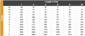
The battery cables I am using are 0 AWG. BIG and thick for less resistance. This has to power the entire truck and start it. 940 CA (740 CCA) can be delivered and I moved the battery to the rear of the truck. So the stock 2 and 4 gauge terminals won't cut it. I would have large voltage drops. So again, look at the chart and I needed exactly 10 feet of cable to route power to the engine harness and only 2 feet to run the ground. So which will handle the max cranking amps this battery can dish out? Yup, 0 guage can handle the load without fail with it actually being OVERKILL for the ground. I could have used 4 or even 6 gauge for that. But now I'm ready for upgrades, dual batteries, and more powerful alternator!
Science, especially electricity is Awesome!
Let's get one thing clear. Stock wiring for use on ANYTHING that doesn't come from the factory is a very bad idea. The wire was chosen to work with a particular load over a specific distance (that's what us engineers do, calculate shit like that). If you introduce a new device (aftermarket cooling fan, more powerful lights, stereo system, etc.) You need to re-engineer the circuit to handle the specified load. You may also need a more powerful battery (or dual batteries) and upgraded charging system (as is the case with powerful stereos).
All my new circuits use a 30-40 amp rated Single Pole Double Throw (SPDT) relays. That means that two pins get accessory power when tripped. One at a time, though. One (pin 87) is normally open so only when tripped does it get power. The other (pin 87a, which I don't use) is normally closed, which means it has power all the time when the relay is not tripped. When you trip the relay 87a loses power. Most cars use a Single Pole Single Throw relay on just about every accessory circuit. Headlights, Brake Lights, Interior lights, Wipers, Fans, Fuel Pumps, etc. Anything that takes a load (measured in Amperes). The relay takes the load so the switch does not have to, preventing the switch from heating up (and potentially burning out or worse causing a FIRE!)
Here is a simple diagram of how an SPDT relay is wired up. For an SPST relay there is no
pin 87a. 4 pins instead of 5, so they are both easy to identify.
This is a diagram of two circuits running through a common fuse block. I will use 12 Gauge wire for the relay power and switched power due to amp draw and the switches only need 16 AWG wire. Well, 18 AWG. would work, but I prefer to go bigger than the math says when you are close to a threshold. Smaller the wire, the more resistance (Ohms) which means higher voltage drops. It also means the wire can become the fuse, which you don't want. That = Fire!
A detail drawing of the fuse block plan and the calculated amp fuse size for each block.
So how do you know what size fuse to use and how big wire you need for each circuit? Well, let's first look at the basic units of measure in Electricity.
Voltage, Amperes, Watts, and Ohms.
V = Volts (Voltage, think of it as pressure to make it easier to understand later) That's our constant for most vehicles (12 Volts).
I = Amps (This measures Current)
r = Ohms (This measures resistance)
W = Watts (Power output).
So what we are solving for is the current draw (amps) to determine which fuse size and wire size we need.
Most things like cooling fans, fuel pumps, wiper motors, etc. measure draw in amps, so it's easy to figure out. But lights are measured in watts meaning you need to do a little math. Let's take my Rock Lights as an example. They are 18 Watt lights each and since I am running 4 lights front (one circuit) and 4 out back (a separate circuit). 4 x 18 = 72 watts total power required on a single circuit. Now we solve for current using this formula. I = W/V or Current = Watts/Volts. In this case 72 Watts/12 Volts = 6 Amps. Thus I will use a 7 Amp fuse for that circuit. Can you use a 10 amp fuse? Sure, but remember, you want the fuse to be the weakest link in the circuit. Safe and easy to replace should you get a spike or short and blow one. With the bigger fuse you make the wire or device it's powering the fuse in the system and we've already said what that can lead to.... Yup FIRE!
What about wire size? Easy, the fastest rule of thumb is use 16AWG to 12 AWG wire for most things. But depending on the distance the power must travel over the wire it will have a voltage drop due to resistance. The larger the wire is the less resistance will be met. Here's a chart I got somewhere that gives you the Amps per Gauge and length of wire. So look at the chart with our data. I need a 14-18 foot run of wire to go to the lights out back. I'm drawing only 6 amps, so you can see that 10 feet 18 AWG will take 15 amps, but remember I'm going a lot farther so we get down to about 6 to 7 amps. So yes, I can run 18AWG but 16 AWG would be safer. Make sense?
The battery cables I am using are 0 AWG. BIG and thick for less resistance. This has to power the entire truck and start it. 940 CA (740 CCA) can be delivered and I moved the battery to the rear of the truck. So the stock 2 and 4 gauge terminals won't cut it. I would have large voltage drops. So again, look at the chart and I needed exactly 10 feet of cable to route power to the engine harness and only 2 feet to run the ground. So which will handle the max cranking amps this battery can dish out? Yup, 0 guage can handle the load without fail with it actually being OVERKILL for the ground. I could have used 4 or even 6 gauge for that. But now I'm ready for upgrades, dual batteries, and more powerful alternator!
Science, especially electricity is Awesome!
Attachments




Last edited:
phattyduck
Elite Member
First, love the thread! So far, I haven't had a reason to post, just lurk and enjoy.
Couple of comments:
- Running the same amount of current through a longer wire doesn't increase the chance of fire, it just wastes power (and may make it so enough power doesn't get to the load). The larger amount of power dissipated in the wire is spread over a longer wire, so each unit of length heats up the same whether it is 1 foot or 100 feet. Otherwise, good info on wire sizing.
- Running a fuse anywhere near its rated load will wear out the fuse with time. You are turning it into a very dim light bulb that will oxidize more quickly than a larger but still safely sized fuse. Set the fuse size to be less than what the rest of the components in the circuit can handle, but with a decent overhead above the normal operation of the circuit - 50%-100% higher, generally. A 10A fuse is probably the right choice for that 6A load. Fusing Guide | 12 Volt Planet
- You'll want to calculate all your (resistive) load currents at 14.5V to make sure you don't undersize any wiring component - also an issue with that 7A fuse on a '6A' load for 12V which then becomes a 7.25A load at 14.5V...
I don't want to see you blowing fuses out on the trail... at least, not during normal use!
-Charlie
Couple of comments:
- Running the same amount of current through a longer wire doesn't increase the chance of fire, it just wastes power (and may make it so enough power doesn't get to the load). The larger amount of power dissipated in the wire is spread over a longer wire, so each unit of length heats up the same whether it is 1 foot or 100 feet. Otherwise, good info on wire sizing.
- Running a fuse anywhere near its rated load will wear out the fuse with time. You are turning it into a very dim light bulb that will oxidize more quickly than a larger but still safely sized fuse. Set the fuse size to be less than what the rest of the components in the circuit can handle, but with a decent overhead above the normal operation of the circuit - 50%-100% higher, generally. A 10A fuse is probably the right choice for that 6A load. Fusing Guide | 12 Volt Planet
- You'll want to calculate all your (resistive) load currents at 14.5V to make sure you don't undersize any wiring component - also an issue with that 7A fuse on a '6A' load for 12V which then becomes a 7.25A load at 14.5V...
I don't want to see you blowing fuses out on the trail... at least, not during normal use!
-Charlie
NotKewl
New member
First, love the thread! So far, I haven't had a reason to post, just lurk and enjoy.
Couple of comments:
- Running the same amount of current through a longer wire doesn't increase the chance of fire, it just wastes power (and may make it so enough power doesn't get to the load). The larger amount of power dissipated in the wire is spread over a longer wire, so each unit of length heats up the same whether it is 1 foot or 100 feet. Otherwise, good info on wire sizing.
- Running a fuse anywhere near its rated load will wear out the fuse with time. You are turning it into a very dim light bulb that will oxidize more quickly than a larger but still safely sized fuse. Set the fuse size to be less than what the rest of the components in the circuit can handle, but with a decent overhead above the normal operation of the circuit - 50%-100% higher, generally. A 10A fuse is probably the right choice for that 6A load. Fusing Guide | 12 Volt Planet
- You'll want to calculate all your (resistive) load currents at 14.5V to make sure you don't undersize any wiring component - also an issue with that 7A fuse on a '6A' load for 12V which then becomes a 7.25A load at 14.5V...
I don't want to see you blowing fuses out on the trail... at least, not during normal use!
-Charlie
Whoops! Forgot about the 14.5v bit. Good catch Charlie, thanks! All my math is off now! The wire size is still good, but I need bigger fuses all around.
Last edited:
NotKewl
New member
More wiring completed tonight. It's slow and tedious, but it's mostly finished. Just have the taillights and rock lights to go and she's fully electrified! Tomorrow, since I took the day off, I plan to actually back it out of the shop for the first time in 6 months (weather permitting). I'd like to do what I should have done BEFORE I started working on it and powerwash all the mud off the undercarriage. A bit of a moot point now I guess, but if I manage to get paint on this thing before trail fest, a good wash will need to happen sooner or later. Keep in mind too, that this wiring and switch pattern is temporary. Just to get me through trail fest. I plan on building a full custom dash setup at some point.
Attachments



Last edited:
NotKewl
New member
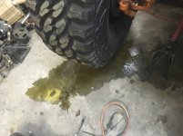
Did you ever see Days of Thunder with Tom Cruise (1990)? You know that scene right before the final race when Robert Duvall's character is talking to the car and looks down to see the oil leaking out of the block and says, "That's not the kind of answer I'm looking for from you!" Yeah, that was me this morning when I grabbed something out of the shop before work. I happened to walk by the old girl and said out loud, "Not long now before you will be hitting the trails." Then I walked around to the front and saw this!
I had flashbacks of High School and Days of Thunder.
I guess putting gear oil in a not quite level (it's sitting on jack stands so I could test drivetrain) axle is one way to figure out that the inner axle tube seal is bad, very bad. If it's even in there, to begin with. :frusty: Maaaaaan, this SUCKS!
I had flashbacks of High School and Days of Thunder.
I guess putting gear oil in a not quite level (it's sitting on jack stands so I could test drivetrain) axle is one way to figure out that the inner axle tube seal is bad, very bad. If it's even in there, to begin with. :frusty: Maaaaaan, this SUCKS!
Attachments

eatpasta
New member
Did you ever see Days of Thunder with Tom Cruise (1990)? You know that scene right before the final race when Robert Duvall's character is talking to the car and looks down to see the oil leaking out of the block and says, "That's not the kind of answer I'm looking for from you!" Yeah, that was me this morning when I grabbed something out of the shop before work. I happened to walk by the old girl and said out loud, "Not long now before you will be hitting the trails." Then I walked around to the front and saw this!
I had flashbacks of High School and Days of Thunder.
I guess putting gear oil in a not quite level (it's sitting on jack stands so I could test drivetrain) axle is one way to figure out that the inner axle tube seal is bad, very bad. If it's even in there, to begin with. :frusty: Maaaaaan, this SUCKS!
View attachment 246696
Oh no!!
...and for those of you that haven't seen it....
Days of Thunder
That sucks! How far behind does this put you do you suppose?
Similar threads

- Replies
- 2
- Views
- 3K

- Replies
- 1
- Views
- 13K

- Replies
- 10
- Views
- 13K


