How To: Make Your Own Rear O2 Simulator for $5

Not certain what you are trying to do, but the flange itself is pretty trivial to replicate if one has access to a machine shop with CNC gear. How thick of a flange spacer is desired? I can get such an item made, and supply the two M8 bolts in a longer configuration to mount the sensor to it. A second gasket may be necessary.


I dont see what this accomplishes except to pull the sensor out of the exhaust stream....is that the point of what you are trying to accomplish?


You just need it out of the stream enough so it’s not reading bad emissions coming from the cat (that’s if your cat is bad, which is usually the P0420 code). Here’s an example of someone using this type of extension.
de9d08e036b200e97fddc1ef823c32f1.jpg
 
Hi Guys , I just tried this modification on my 2002 Toyota 4Runner. I actually used a 4.7microfarad capacitor and the 1M-Ohm resistor. Prior to this modification the o2 sensor monitor always set easily and the catalyst threw the p0420 code. Afterwords, the catalyst monitor set, however the computer threw the p0136 code. This apparently means that: "(The P0136 code is set when the Engine Control Module (ECM) detects that the rear O2 sensor signal voltage is out of range for an extended period of time)".

Do you have any input on what I can do to correct this? Could the different capacitor have messed with the data?

Thanks

Hi - Bumping an old post here as I have the same issue with this mod on my '04 Tacoma 3.4L I used the same R/C set up, and am now getting P0136. Hoping that you or someone found a fix. Thx!
 
There is a plus and minus for the diode and the Cap.


Sent from my iPhone using Tapatalk

I did put the negative for the capacitor on the white.
I don't have a diode, just a resistor and capacitor, same as the diagram posted earlier in this thread. (1Mohm resistor, 4.7uF capacitor).
 
Do you have live data to read the sensor?

Sent from my iPhone using Tapatalk

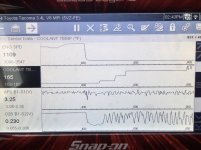
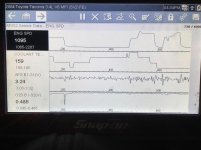
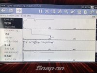
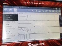
Sure do... (courtesy a buddy who let me borrow his snappy scanner)... see attached...before and after for low RPMs and then higher RPMs (in that order).

Note the erratic readings / high range before for O2S B1 S2, and pretty steady at about 0.5V after in both conditions.

I had an extra sensor, so I built the circuit twice to make sure I didn't mess it up, and got pretty much the same set of results.
 

Attachments

  • IMG_0816.jpg
    IMG_0816.jpg
    133.2 KB · Views: 1,140
  • IMG_0879.jpg
    IMG_0879.jpg
    125.1 KB · Views: 1,146
  • IMG_0814.jpg
    IMG_0814.jpg
    138.1 KB · Views: 1,143
  • IMG_0882.jpg
    IMG_0882.jpg
    128 KB · Views: 1,123
Last edited:
I think that the one screen image showing your sensor at a steady voltage is the cause for the code. It’s expecting to see a voltage swing like the front sensor but not in phase with it and at a lower voltage.

It looks like if it stays steady too long above 31mph with engine up to temp it will produce the code.

Did you solder everything?


Sent from my iPhone using Tapatalk
 
Did you solder everything?

Sent from my iPhone using Tapatalk

Yup, sure did. I snipped off portions of a terminal strip for the connections so I had something solid to work with versus soldering to the wires. Feel pretty confident the connections are good. I'll snap a pic and post a little later.

I see what you mean about the flatline voltage... could this be related to the capacitor? I used a 4.7uF, not a 1uF...
 
Yup, sure did. I snipped off portions of a terminal strip for the connections so I had something solid to work with versus soldering to the wires. Feel pretty confident the connections are good. I'll snap a pic and post a little later.

I see what you mean about the flatline voltage... could this be related to the capacitor? I used a 4.7uF, not a 1uF...


It’s possible....but I thought the cap did more of a phase shift. To me the larger cap will slow down the voltage rise and fall. It’s been 1987 since I had DC theory which included cap charge times but I guess it’s possible to size it so you almost match the rise and fall and it becomes a pretty level signal.

I tried making mine work countless ways and it looked like what I was seeing would make the 0420 code clear. It ended up being antifreeze.


Sent from my iPhone using Tapatalk
 
Thanks to the OP for this info. I fabbed the little circuit, potted it, reinstalled, and have been unable to cause a CEL/code. My 86 4runner 5VZ-FE swap is done. Thanks again!!
 
Unless your current catalytic converter(s) is clogged then any increase in hp will be very small.

Sounds about right. I have a 2004 Tacoma with 253k on the clock that keeps throwing the inefficient cat code. It's pretty much just our ranch truck. It seems to run just fine. Just not sure how I want to proceed with it.
 
Last edited:
Does anyone know if this mod will work for an 06 with the VVT-i 4.7 V8?

I am installing some Doug Thorley long tube headers and Y pipe - went to URD and they are no longer offering the rear O2 sim due to "bullying of small businesses by the EPA".

Now I'm worried about performance issues if I can't figure out the rear O2 issue.

TYIA!
 
Wrong Colors

Hey, so I went to complete this setup and when I pulled my down stream O2 sensor, the colors don’t match. I have two whites, a black, and a grey wire. Has anyone found this on their Toyota? Running a 1997 Tacoma. Thanks!
 

Members online

Forum statistics

Threads
278,316
Messages
3,554,120
Members
248,016
Latest member
Advally Service

Trending content

Back
Top