In over my head--roof rack lights wiring questions

OK good. That is at least the correct connector. However you should verify that the green wire is the positive wire. I'd don't see how you would have lights at your switches if it were not, but I would double check just to be sure. Do your switch lights dim when you adjust the gauge dimmer?

Ohh, and the other wire will of course be a ground.

Also - have you checked to see if your roof rack is connected to ground? Even if it is not, it should be fairly simple to run a short wire from the rack to one of the mounting bolts which should definitely be connected to chassis ground. Then you just ground your lights to the rack.

The bolt I circled in blue right here should be grounded to the chassis ground?

0zD8qS6.jpg


If that's true, that would make things way easier.

Also, I'm trying to decide how to get the power wires through the firewall. I haven't found a suitable spot that's already available, so I'm thinking of drilling a hole where the red dot is in this picture:

BmgWitq.jpg


Here's a wider view:

hhhnEer.jpg


And I think that would come out somewhere within the red circle here:

YM7A3vC.jpg


Anything I have to worry about drilling through in that spot? Or is there a better way to get all of these wires through the firewall?
 
Last edited:
The bolt I circled in blue right here should be grounded to the chassis ground?

0zD8qS6.jpg


If that's true, that would make things way easier.

Also, I'm trying to decide how to get the power wires through the firewall. I haven't found a suitable spot that's already available, so I'm thinking of drilling a hole where the red dot is in this picture:

BmgWitq.jpg


Here's a wider view:

hhhnEer.jpg


And I think that would come out somewhere within the red circle here:

YM7A3vC.jpg


Anything I have to worry about drilling through in that spot? Or is there a better way to get all of these wires through the firewall?

Go through the grommet right there. Right next to where you are going to drill that hole. You can feed the wires through there. That's where all my wires are run through.

that bolt MIGHT work, but might not.
 
You'll need to check what that bolt threads into. If it threads into the roof sheet metal it will work.

I plan to drill my grommet holes in that area but you can use that grommet like Doc said. Just be sure not to damage the existing wires.
 
That bolt is where I grounded mine. As for going through the firewall I went through the rubber grommet right next to your red dot. I didn't want to poke a ton of holes in the firewall. You can use a metal coat hanger to make it easier to feed the wires through. I used black RTV to keep it watertight.

I'm not sure why you are having issues with lights. I used the wire from the clock since I replaced the clock with a volt meter and had an extra wire.

Sorry I didn't respond sooner. I've been in the shop working on my own shit box.
 
Go through the grommet right there. Right next to where you are going to drill that hole. You can feed the wires through there. That's where all my wires are run through.

that bolt MIGHT work, but might not.

That grommet was actually my first plan, but my first attempts were futile at piercing it with a coat hanger. However, after seeing that you did it, I tried again and I was able to get the coat hanger through it now, and will try to feed the wires through using that.

That bolt is where I grounded mine. As for going through the firewall I went through the rubber grommet right next to your red dot. I didn't want to poke a ton of holes in the firewall. You can use a metal coat hanger to make it easier to feed the wires through. I used black RTV to keep it watertight.

I'm not sure why you are having issues with lights. I used the wire from the clock since I replaced the clock with a volt meter and had an extra wire.

Sorry I didn't respond sooner. I've been in the shop working on my own shit box.

Well that's going to make things way easier, I'll ground it to that bolt too and not worry about running the ground wires all the way back down into the cab.

And I have awesome news... all of my lights are working now! No clue what I did, I really didn't mess with anything again, I had been working on other stuff, but I went to start it up just now to move it and all the lights came on. The gauge lights even seem to be all on now, as opposed to just one or two being on before. Today is my lucky day apparently.

Thanks again for all the help everyone. I wouldn't even be attempting this if it wasn't for this great community :thumb3:
 
If you take a sharp knife is possible to cut a slit in the firewall grommet, but if your thinking of passing alot of wires though its easier to cut a separate just for wiring going to and from the switches
 
I tried doing that, but was scared about cutting one of the wires that goes through that grommet. With my luck, it would have happened haha. I was able to get the 6 wires through the grommet using the old coat hanger trick though, so everything is good to go now.

Just have to hook up the Blue Sea block to the fuse and battery now, and ground the relays and do the add-a-circuit for the switch power, and I should be able to test out all of the switches tonight to find out if my wiring is correct.
 
Why not just do something similar to what I did?

I put a gound and power stud on each side of the box, so that way there's only two wires going to and leaving.

All my power wires go to one stud, all the ground to another.

You would've only had to take two wires instead of six then.

Just a thought.
 
I have 5 different sets of lights that I want to be able to turn on independently of each other, so they all had to go to a separate terminal on the aux fuse block. The 6th wire is the power wire for the rock lights, so that had to get through somehow too. All of the grounds are going to be grounded to one spot though.

Unless I'm not understanding how that would work. If that way would still let me turn on the lights independently of each other, well, I guess I did it the hard way then haha. Oh well, they're already through, no going back now.

Edit: The more I think about it, the more your way is starting to make sense. Oh well. I guess the only upside to the way I did it is that each of the lights are on their own fuse.
 
Last edited:
Dammit. That's genius. Why didn't I see that before? If anyone is thinking about following this as a guide in the future, do that ^ instead of what I did haha.

Just found that in your build thread. I added the link to the first post as well. There's a lot of good info and pictures in your thread!
 
Last edited:
Thanks man!

I spent many a sleepless night trying to figure out a different way to run the switches and the wiring.

The Biomedical Engineering guys here @ NHCL thought it was pretty impressive as well! Lol.

I know you've got yours set up, but if you ever change your mind, let me know. I can make ya one. :)
 
entire post
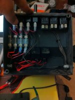
So are mine. Each switch is run to a 35 amp fuze, which is run to the power stud. each relay is run to the power stud for power. Each switch is then run to each relay, and each relay is then run out the back of the box. Like so:

Dammit. That's genius. Why didn't I see that before? If anyone is thinking about following this as a guide in the future, do that ^ instead of what I did haha.

Just found that in your build thread. I added the link to the first post as well. There's a lot of good info and pictures in your thread!

Thanks man!

I spent many a sleepless night trying to figure out a different way to run the switches and the wiring.

The Biomedical Engineering guys here @ NHCL thought it was pretty impressive as well! Lol.

I know you've got yours set up, but if you ever change your mind, let me know. I can make ya one. :)

That's a really good idea. Just make sure you use some big ass wire when you make the run from the battery to the box. If you go too small and turn all the circuits on at the same time it could burn some stuff up. I would also put a fuse on the wire run from the battery to the box.
 
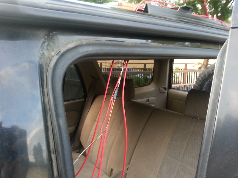
Well, this project is almost done. I have the wires ran up to the roof, and the roof rack itself is just about all wired up too. Here's some pictures of running it to the roof:


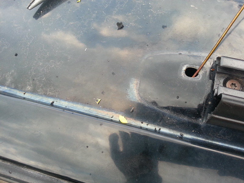
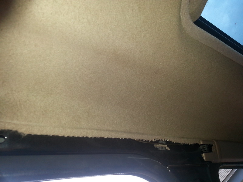
You can see the coat hanger poking through the headliner here:


And here it is, with the wires up through it:


I'm going to put some RTV on that hole, then see about drilling a hole in the rail end cap, and maybe putting a rubber grommet in it and running the wires up through that. We'll see how it goes!
 
Last edited:
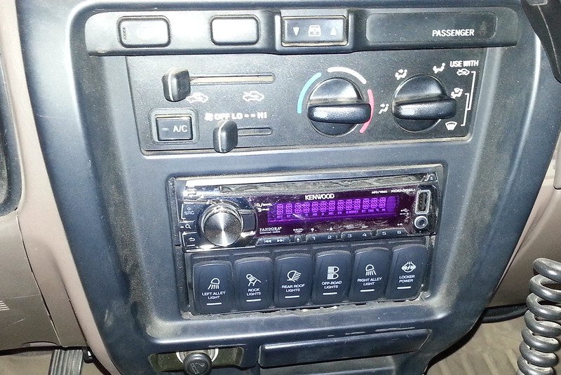
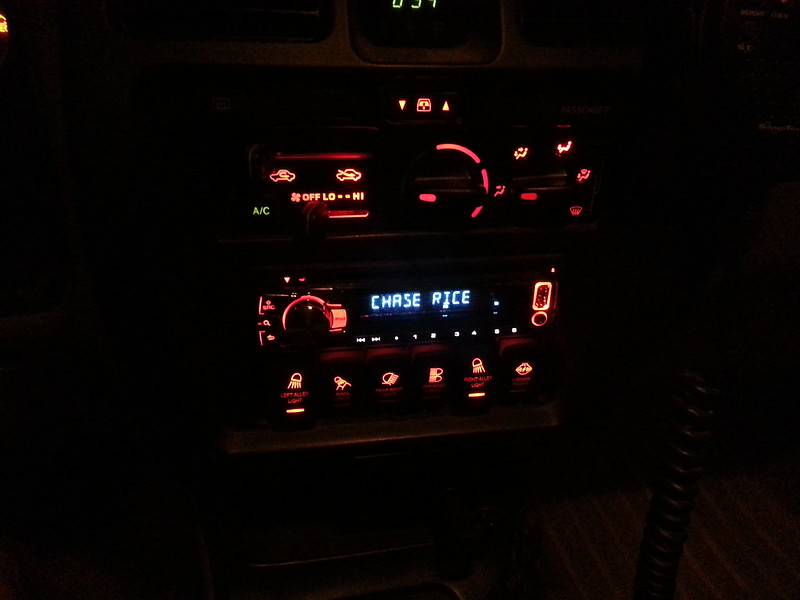
It has come to my attention that I never finished this thread off with pictures of the switches installed. So, without further ado, here they are:


The pictures kind of suck, because they were taken with a camera phone at night, but oh well. [MENTION=95329]txbonds[/MENTION] If you do it this way, and you have to cut the center trim piece, I recommend taking your time on it, because as you can see, I kind of did it sloppy haha. Oh well though, that's just my style :rockon:
 
Last edited:
Accessory wiring help

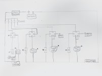
Is there anything wrong with this wiring diagram? I’d take any help on locating the hi beam and the reverse wires to tap into.
 

Attachments

  • E8CF07BD-560F-48B7-B22B-5162B06B7D3D.jpg
    E8CF07BD-560F-48B7-B22B-5162B06B7D3D.jpg
    107.8 KB · Views: 113

Members online

No members online now.

Forum statistics

Threads
278,315
Messages
3,554,125
Members
248,016
Latest member
Advally Service

Trending content

Back
Top