
You are using an out of date browser. It may not display this or other websites correctly.
You should upgrade or use an alternative browser.
You should upgrade or use an alternative browser.
Rock Rat's Imperial Jade Mica "Next Adventure" Build
- Thread starter Rock_Rat
- Start date


Rock_Rat
Senior Member
Engine Bay Wiring Harness for Paranoid Fabrication Bracket
This weekend I had a chance to work on the harness assembly that runs from the paranoid fabrication bracket attached to my radio out to my engine bay.
The link to the male end of the harness is here Male Harness for Paranoid Fab Bracket.
Steps in the process and materials used
Inside the harness assembly are six uniquely colored wires for switching, a power and a ground. The colored wires will match up with the 16gauge wires on the relays. Outside the harness (hidden from the photo) is one pwr wire that is installed inside the cabin to the ashtray connector. This way the switches are only lit when the lights are on. Red wires are only needed for the upper and lower lights on the switch.
For now all lights will be switched from power and with the key in the accessory position. .
Inside the cockpit are the wires I pulled through the engine bay. The spools are outside. Notice I have my tools for crimping and ready to go.
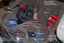
Slide plenty of the sleeving on so you you can pull it back through the engine bay. Once pulled through you can trim it as necessary. Install only one piece of heat shrink. No need to install it on the engine bay side yet until you determine how much wire you'll need.
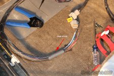
I didn't measure how long the harness is, but it's plenty long to pull through the engine bay and connect to a Blue Sea fuse block. I used a small amount of super lube on the tape.
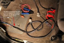
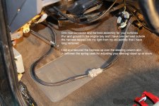
Here's a good photo of the harness pulled through. In this photo the wires are still running off spools on the floor. Once I determined "about" how much wire I would need I cut them and zip tied them all together. Ready for the engine bay installation with my relays and blue Sea fuse box.
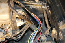
Her'es a good photo of the Deutsch connector connected. Obviously, I pulled all the slack in on the engine bay side. I chose to route the harness in back of the AC/Heat ducting over the steering column and away from the adjuster spring. I found a very stout wiring harness on the left that I was able to secure the harness to.
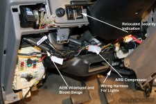
This final photo shows several harnesses. There's one in the front that goes to both of my AEM gauges. I also have one for my ARB compressor with extra connections for e-Lockers. Off to the far right is the harness for the lights.
This weekend I had a chance to work on the harness assembly that runs from the paranoid fabrication bracket attached to my radio out to my engine bay.
The link to the male end of the harness is here Male Harness for Paranoid Fab Bracket.
Steps in the process and materials used
- Using a stiff wire, gently enter it through the firewall from the engine bay inside the drivers side area.
- Take the eight spools of wire and tape them to the wire and put a little super lube on it and gently pull wires through inside the cab.
- Pull PLENTY of wire through and strip wires back 5/16".
- Using a Deutsch pin crimper, crimp the pins onto the wire.
- Take your solid (not split) tech flex braided sleeving and slide PLENTY onto the wire. Pull as much wire through the cab as needed. You can always pull it back through later.
- Slip ONLY ONE piece of heat shrink on the end inside the cab.
- Now it's time to pin your connector. Ensure wires mate up to the male pins. (IE: red-red, purple-purple, green-green etc.) Double and triple check.
- Work the tech flex so it's pretty tight and using a heat gun, install the heat shrink. You're finished with the harness inside the cab.
- Now tape up the engine bay end and pull through the firewall until you're pleased with the length inside the cab. Give yourself some slack so you can easily remove your radio, console panel as needed with just one simple disconnect.
Inside the harness assembly are six uniquely colored wires for switching, a power and a ground. The colored wires will match up with the 16gauge wires on the relays. Outside the harness (hidden from the photo) is one pwr wire that is installed inside the cabin to the ashtray connector. This way the switches are only lit when the lights are on. Red wires are only needed for the upper and lower lights on the switch.
For now all lights will be switched from power and with the key in the accessory position. .
Inside the cockpit are the wires I pulled through the engine bay. The spools are outside. Notice I have my tools for crimping and ready to go.
Slide plenty of the sleeving on so you you can pull it back through the engine bay. Once pulled through you can trim it as necessary. Install only one piece of heat shrink. No need to install it on the engine bay side yet until you determine how much wire you'll need.
I didn't measure how long the harness is, but it's plenty long to pull through the engine bay and connect to a Blue Sea fuse block. I used a small amount of super lube on the tape.
Here's a good photo of the harness pulled through. In this photo the wires are still running off spools on the floor. Once I determined "about" how much wire I would need I cut them and zip tied them all together. Ready for the engine bay installation with my relays and blue Sea fuse box.
Her'es a good photo of the Deutsch connector connected. Obviously, I pulled all the slack in on the engine bay side. I chose to route the harness in back of the AC/Heat ducting over the steering column and away from the adjuster spring. I found a very stout wiring harness on the left that I was able to secure the harness to.
This final photo shows several harnesses. There's one in the front that goes to both of my AEM gauges. I also have one for my ARB compressor with extra connections for e-Lockers. Off to the far right is the harness for the lights.
Attachments






Last edited:


Formidable
New member
Amazing build and attention to detail. Well done!

Unner
New member
Your attention to detail is amazing! Did you only mount the awning brackets, or did you mount the awning also? If you did mount the awning do you have any pictures?
Also, those Maxtraxx mounts, what exactly are they? I'm debating a more permanent mount for my Tred Pros, at least something more than ratchet straps to the rack when I go out wheeling.
Also, those Maxtraxx mounts, what exactly are they? I'm debating a more permanent mount for my Tred Pros, at least something more than ratchet straps to the rack when I go out wheeling.

Road Bull
Senior Member
Looking great Mike! Wow, your rig is just getting better and better. Super charger, sweet rack enhancements, all sorts of switches to play with...
I really love those Whitson racks. It's a shame that you can't get them anymore. I dig that profile, but I don't want to support Gobi to get it, lol. I might have my welder friend build a custom rack instead. I love how it is low profile and super sturdy.
Keep up the good work!
I really love those Whitson racks. It's a shame that you can't get them anymore. I dig that profile, but I don't want to support Gobi to get it, lol. I might have my welder friend build a custom rack instead. I love how it is low profile and super sturdy.
Keep up the good work!

Rock_Rat
Senior Member
Nice wiring work! I have had my paranoid fab bracket for months...I am not looking forward to this portion but you may have motivated me. I still need to order a few more switches though.
Hey thanks! That's great that I got you motivated! If you need any help, feel free to post up on my page. There's so many ways and options you can do your wiring. switched power, switched ground, lights, accessory, hot etc... It's still pretty easy stuff. A cheap way to color code your wiring is with sharpies. I saw how someone did that it way.
Your attention to detail is amazing! Did you only mount the awning brackets, or did you mount the awning also? If you did mount the awning do you have any pictures?
Also, those Maxtraxx mounts, what exactly are they? I'm debating a more permanent mount for my Tred Pros, at least something more than ratchet straps to the rack when I go out wheeling.
Thanks Unner. coming from you that means a lot. I did not mount my awning but I can do that for you and take a few pics this weekend. I was limited on my choice of brackets because of the antenna and the light mount already welded to my rack. Went with an ARB 2500 based on some valuable feedback from others with awnings. I also went with the drivers side because it will be in the way of the snorkel on the passenger side later on.
Honestly, as for the (MAXSA Innovations - is what I have) traction devices you can always zip tie them to your rack. That's normally what I've done when I headed out wheeling. But you have a tire carrier so you should be able to secure them in the back with ratchet straps and not on your rack. The bolts on the rack are just temporary for the winter. It was really simple and an option for you as well. Couple of fender washers and a nut on the bolt, slip your treds over the top and use a wingnut to secure them down.
Amazing build and attention to detail. Well done!
Thanks for the compliment. Much appreciated. Look forward to your build on here soon. Pretty color rig BTW. One of my favorites aside from the IJM.
Looking great Mike! Wow, your rig is just getting better and better. Super charger, sweet rack enhancements, all sorts of switches to play with...
I really love those Whitson racks. It's a shame that you can't get them anymore. I dig that profile, but I don't want to support Gobi to get it, lol. I might have my welder friend build a custom rack instead. I love how it is low profile and super sturdy.
Keep up the good work!
Thank you sir! Well thought out as you know. Lots of mental planning and research. You remember I picked up that rack during lunch one day locally. It popped up on CL and I actually had to run all the way home to swap vehicles. Have you looked at the Frontrunner rack? If I didn't have the Whitson rack I would have gone with the entire Frontrunner setup. Extremely versatile.
Awesome work on the switch panel! I love the way you did the wiring. I wish I had done it that way, it is so much cleaner- I'm just worried about changing something up and having to redo the entire thing.
Thanks! As long as your lights work and it's pretty tidy in there it's all good no matter what it looks like. Oh, and SAFE. You could still build a connector now and change it out later on.
Rock_Rat
Senior Member
Relocating VIP Security Sensor Indication
It was NOT my intention to relocate the sensor/indication for my factory security system, but when I was finishing up my harness for my lights I noticed how much room there was behind the panel next to my ATRAC switch.
I also saw that other year 4Runners have it there so for the life of me, I was wondering why my 2001 model had it where it was.
So, not a big deal for most but here goes:
Pretty simple steps as follows:
So for me, it opened up an additional slot for a switch or perhaps a remote connection for the Warn winch. I'm still undecided as to what I'll do with it but at least it's there and it fell in place with the work I was doing this past weekend.
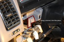
You'll need to trim this small piece of plastic so the back of the sensor will fit.
Measure out the size of the sensor and ensure it fits tightly in there. DON'T cut it out too big. Go small and use a tiny file to smooth out the edges as needed.
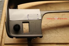
I soldered about a four inch extension to each of the connectors and then sealed it up with electrical tape and heat shrink. This gives me plenty of room to move the panel around and access anything behind it.
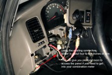
And here's the finished product with the additional space available for another switch, plug-in for hand-held mic, winch control plug-in, USB panel etc...and the obvious an e-locker switch.
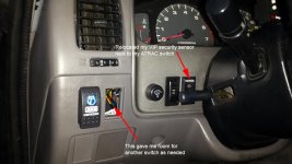
It was NOT my intention to relocate the sensor/indication for my factory security system, but when I was finishing up my harness for my lights I noticed how much room there was behind the panel next to my ATRAC switch.
I also saw that other year 4Runners have it there so for the life of me, I was wondering why my 2001 model had it where it was.
So, not a big deal for most but here goes:
Pretty simple steps as follows:
- Remove panel.
- Measure and cut a place holder for the sensor next to the steering column.
- Trim the back support plastic as needed using a dremel.
- Disconnect or cut wires going to your sensor.
- Solder and heat shrink about a four to six inch extension going to the sensor.
So for me, it opened up an additional slot for a switch or perhaps a remote connection for the Warn winch. I'm still undecided as to what I'll do with it but at least it's there and it fell in place with the work I was doing this past weekend.
You'll need to trim this small piece of plastic so the back of the sensor will fit.
Measure out the size of the sensor and ensure it fits tightly in there. DON'T cut it out too big. Go small and use a tiny file to smooth out the edges as needed.
I soldered about a four inch extension to each of the connectors and then sealed it up with electrical tape and heat shrink. This gives me plenty of room to move the panel around and access anything behind it.
And here's the finished product with the additional space available for another switch, plug-in for hand-held mic, winch control plug-in, USB panel etc...and the obvious an e-locker switch.
Attachments




Unner
New member
Thanks Unner. coming from you that means a lot. I did not mount my awning but I can do that for you and take a few pics this weekend. I was limited on my choice of brackets because of the antenna and the light mount already welded to my rack. Went with an ARB 2500 based on some valuable feedback from others with awnings. I also went with the drivers side because it will be in the way of the snorkel on the passenger side later on.
Honestly, as for the (MAXSA Innovations - is what I have) traction devices you can always zip tie them to your rack. That's normally what I've done when I headed out wheeling. But you have a tire carrier so you should be able to secure them in the back with ratchet straps and not on your rack. The bolts on the rack are just temporary for the winter. It was really simple and an option for you as well. Couple of fender washers and a nut on the bolt, slip your treds over the top and use a wingnut to secure them down.
Whenever you get a chance is good! I'll have to think about a way to mount the Tred Pros, especially if I do Moab in March. I like the idea of the bolts through the roof rack, but it can also be nice to lay up there when the weather is nice and a bolt in your back is not so nice


MattJakobs
New member
Great last few posts with good detail. You have officially inspired me to learn a bit more about wiring and really clean all my stuff up. Something that could probably stand to be done
Rock_Rat
Senior Member
Great last few posts with good detail. You have officially inspired me to learn a bit more about wiring and really clean all my stuff up. Something that could probably stand to be done
I'm glad it has inspired you. I'm thinking about doing a video to help get guys moving in the right direction for installing all of their lights and other accessories. It would cover things like wire selection, switches, relays, fuses etc. I'll probably do this once I install my winch.
MattJakobs
New member
I'm glad it has inspired you. I'm thinking about doing a video to help get guys moving in the right direction for installing all of their lights and other accessories. It would cover things like wire selection, switches, relays, fuses etc. I'll probably do this once I install my winch.
If you make a video, I will absolutely watch it. I was actually on YouTube last night looking for a video about how to wire switches grounds and power together. It appears that that's what you did but again, I don't know much in the electrical category and just started really looking into it.
If you do happen to make this video, please keep me posted about it.
Rock_Rat
Senior Member
The following pics are with the ARB 2500 x 2500 installed on the Whitson Rack. You can find the brackets I used in this post in my build. Brackets for ARB and Whitson Rack [MENTION=116387]Unner[/MENTION] here's some pics just for you. You owe me a beer.
A few things about my thought process on the installation.
So I went with the driver's side only because I plan on installing a snorkel one day. That was my only deciding factor. Thanks to [MENTION=138432]Liquidmantis[/MENTION] for providing that insight. OK and the few extra feet to get the beer! Thanks Alex.
I also went with an ARB based on some users information about the quality of ARB over the CVT design. With the CVT, it had a tendency to sag and it seemed you had to push the awning up out of the way to open the doors. That may also be the case with an ARB if it's mounted on a very low profile rack such as a FrontRunner design. (Hated to not go local but had to make the hard choice here.)
I chose the 2500 x 2500 again, based on our great forum members inputs. If you go with the shorter awning and it starts to rain, you can't sit side-by-side without getting wet. You end up having to sit fore and aft. So I decided to go full width.
Here are some pictures of it mounted and again, you can go to my previous post about why I chose the mounting brackets that I did. I hope this helps you in making your own decision if and when you decide to purchase an awning.
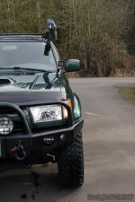
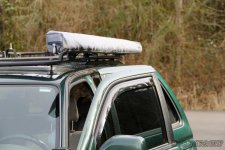
Forward facing picture. You can see how tightly it fits up against the rack and doesn't hang over the doors.
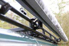
Her's a "birds-eye" view of the mounts and the awning. The nice thing about having the gussets outside the rack is they don't take up any room inside the rack.
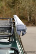
Here's a view with both doors opened. As you can see, there is plenty of room. I'm 6'2" and it sits above my head easily.
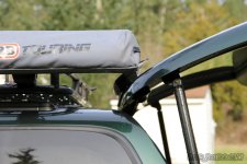
Here's a picture of my rear cargo door fully opened. Again, plenty of room.
My biggest decision on using these brackets was not losing the ability to use my side light mounting bracket. From this angle it's hard to see but I have PLENTY of room to mount a light (upside down) using my existing bracket. I could actually mount a cube up there if I wanted to.
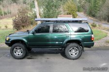
Side profile of the awning. Sitting in the rig driving, I cannot see it at all. This I like!
If there's any reason to go full width, this would be it for me. You can sit comfortably side-by-side. The bag in the middle is the room to go with the awning.
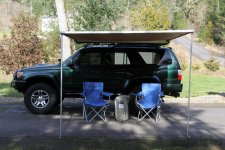
OK and one last picture from looking at it head on. Very pleased with how it all turned out.
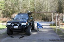
A few things about my thought process on the installation.
- First I asked the forum which side they mounted their awning and if they had a specific reason why. Link is here Which Side to Mount ARB Awning
- I also sent out a few PM's about which awning and which size. Thanks for responding back [MENTION=82154]GSPRunner[/MENTION] and [MENTION=63487]A.Wilson013[/MENTION] Your insight was very informative and helped me make the right decision.
So I went with the driver's side only because I plan on installing a snorkel one day. That was my only deciding factor. Thanks to [MENTION=138432]Liquidmantis[/MENTION] for providing that insight. OK and the few extra feet to get the beer! Thanks Alex.
I also went with an ARB based on some users information about the quality of ARB over the CVT design. With the CVT, it had a tendency to sag and it seemed you had to push the awning up out of the way to open the doors. That may also be the case with an ARB if it's mounted on a very low profile rack such as a FrontRunner design. (Hated to not go local but had to make the hard choice here.)
I chose the 2500 x 2500 again, based on our great forum members inputs. If you go with the shorter awning and it starts to rain, you can't sit side-by-side without getting wet. You end up having to sit fore and aft. So I decided to go full width.
Here are some pictures of it mounted and again, you can go to my previous post about why I chose the mounting brackets that I did. I hope this helps you in making your own decision if and when you decide to purchase an awning.
Forward facing picture. You can see how tightly it fits up against the rack and doesn't hang over the doors.
Her's a "birds-eye" view of the mounts and the awning. The nice thing about having the gussets outside the rack is they don't take up any room inside the rack.
Here's a view with both doors opened. As you can see, there is plenty of room. I'm 6'2" and it sits above my head easily.
Here's a picture of my rear cargo door fully opened. Again, plenty of room.
My biggest decision on using these brackets was not losing the ability to use my side light mounting bracket. From this angle it's hard to see but I have PLENTY of room to mount a light (upside down) using my existing bracket. I could actually mount a cube up there if I wanted to.
Side profile of the awning. Sitting in the rig driving, I cannot see it at all. This I like!
If there's any reason to go full width, this would be it for me. You can sit comfortably side-by-side. The bag in the middle is the room to go with the awning.
OK and one last picture from looking at it head on. Very pleased with how it all turned out.
Attachments
-
 ARB 2500 Installed_1.jpg117.1 KB · Views: 1,336
 -
 ARB 2500 Installed_2.jpg75.4 KB · Views: 1,343
 -
 ARB 2500 Installed_3.jpg106.6 KB · Views: 1,378
 -
 ARB 2500 Installed_4.jpg83.8 KB · Views: 1,463
 -
 ARB 2500 Installed_5.jpg94.7 KB · Views: 1,391
 -
 ARB 2500 Installed_6.jpg138.6 KB · Views: 2,516
 -
 ARB 2500 Installed_7.jpg139.4 KB · Views: 1,376
 -
 ARB 2500 Installed_8.jpg138.4 KB · Views: 1,506
Last edited:
Rock_Rat
Senior Member
How to Wire a Six Switch Paranoid Fabrication Bracket
This little tutorial will help you wire a six switch specifically designed for the Paranoid Fabrication bracket, or any switch or series of switches regardless of where they're located. My hope is for those that are intimidated by working with electrical systems, that this will you overcome your hesitation and help increase your confidence and understanding. I'll preface this by saying that I will not be able to finish this all in one sitting or even this week. My recommendation would be for you to subscribe to this thread/build. I have a lot of other home projects that I need to take care of. Anyway here's some photos to get you started.
A pointer or two for you. Electricity is nothing to be feared, only respected. If you have problems grasping electrical systems, think of the wires like the plumbing in your house or a water sprinkler system. Wires carry current instead of water. [MENTION=102597]IBallEngineer[/MENTION] is by far the most respected member on here with electrical knowledge. Ask questions.
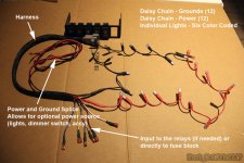
Making daisy chains is pretty easy. Just slice (preferred) or cut the wires to the length you want and install the female terminal ends. They DO NOT need to be weatherproof or heat shrinked. That's just my option for strength. Pure overkill. EDIT: Notice the two different connectors. The light blue connectors are for 16AWG because I'm using "two" wires (even though it's one) in the daisy chain. I'm finishing it off with a single wire that goes into the 18AWG connector.
There are MANY switch options (SPST, SPDT, DPDT, with lights, without lights, etc....)available with many different personalities of operation. Keep in mind they ALL do basically the same thing. They are designed to send a request for something to your power source. "Please turn on my lights". - BAM - Here are your lights! Now "Turn them off" - BAM - You're in the dark.
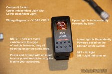
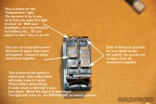
The rear of the SPST (on/off switch with two lights). The INDEPENDENT light let's me know I have power, the DEPENDENT light let's me know it's in the ON or OFF position.
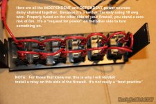
Simple little daisy chain connecting all of my power leads off the switch to my power of choice. I decided to go with the accessory power in the JB under the dash using an "add-a-circuit" from Bussman. My specific wire that I'm using is spliced into my power (red) wire in my harness. I also have a ground that I could use if I wanted to use my dimmer. It works off of power and Gnd. The red wire in my 8-pin harness that goes through the firewall is not being used. However, I still have the option of hooking it up directly to the battery, my DRL's, headlights, and any other circuit in the engine bay. This gives me many other choices. Keep in mind, that wire is HOT when I have the ignition key in the ON position. Therefore it must be secured very safely.
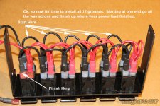
A ground is a ground. Since I'm going through a relay, I want to make sure I have a quality ground. Electricity is always ground seeking. Relays aren't any different. The current will run through the relay until it finds a ground.
Just another view of the power and grounds.
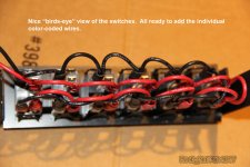
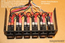
And here's a picture of the entire six switches all connected ready to be installed. The color coded wires will go to a color coded relay or directly to a terminal block that is fused.
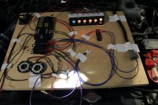
This final photo is just a teaser to show you what's ahead. I built a working model of my switches with fuse box, terminal block, and relays. I'll walk you through this a step at a time.
This little tutorial will help you wire a six switch specifically designed for the Paranoid Fabrication bracket, or any switch or series of switches regardless of where they're located. My hope is for those that are intimidated by working with electrical systems, that this will you overcome your hesitation and help increase your confidence and understanding. I'll preface this by saying that I will not be able to finish this all in one sitting or even this week. My recommendation would be for you to subscribe to this thread/build. I have a lot of other home projects that I need to take care of. Anyway here's some photos to get you started.
A pointer or two for you. Electricity is nothing to be feared, only respected. If you have problems grasping electrical systems, think of the wires like the plumbing in your house or a water sprinkler system. Wires carry current instead of water. [MENTION=102597]IBallEngineer[/MENTION] is by far the most respected member on here with electrical knowledge. Ask questions.
Making daisy chains is pretty easy. Just slice (preferred) or cut the wires to the length you want and install the female terminal ends. They DO NOT need to be weatherproof or heat shrinked. That's just my option for strength. Pure overkill. EDIT: Notice the two different connectors. The light blue connectors are for 16AWG because I'm using "two" wires (even though it's one) in the daisy chain. I'm finishing it off with a single wire that goes into the 18AWG connector.
There are MANY switch options (SPST, SPDT, DPDT, with lights, without lights, etc....)available with many different personalities of operation. Keep in mind they ALL do basically the same thing. They are designed to send a request for something to your power source. "Please turn on my lights". - BAM - Here are your lights! Now "Turn them off" - BAM - You're in the dark.
The rear of the SPST (on/off switch with two lights). The INDEPENDENT light let's me know I have power, the DEPENDENT light let's me know it's in the ON or OFF position.
Simple little daisy chain connecting all of my power leads off the switch to my power of choice. I decided to go with the accessory power in the JB under the dash using an "add-a-circuit" from Bussman. My specific wire that I'm using is spliced into my power (red) wire in my harness. I also have a ground that I could use if I wanted to use my dimmer. It works off of power and Gnd. The red wire in my 8-pin harness that goes through the firewall is not being used. However, I still have the option of hooking it up directly to the battery, my DRL's, headlights, and any other circuit in the engine bay. This gives me many other choices. Keep in mind, that wire is HOT when I have the ignition key in the ON position. Therefore it must be secured very safely.
A ground is a ground. Since I'm going through a relay, I want to make sure I have a quality ground. Electricity is always ground seeking. Relays aren't any different. The current will run through the relay until it finds a ground.
Just another view of the power and grounds.
And here's a picture of the entire six switches all connected ready to be installed. The color coded wires will go to a color coded relay or directly to a terminal block that is fused.
This final photo is just a teaser to show you what's ahead. I built a working model of my switches with fuse box, terminal block, and relays. I'll walk you through this a step at a time.
Attachments
-
 Harness_1.jpg122.7 KB · Views: 1,474
 -
 Harness_2.jpg106.5 KB · Views: 1,356
 -
 Harness_3.jpg118.4 KB · Views: 1,325
 -
 Harness_4.jpg120.6 KB · Views: 1,423
 -
 Harness_5.jpg135.3 KB · Views: 1,445
 -
 Harness_6.jpg95.1 KB · Views: 1,301
 -
 Harness_7.jpg137.7 KB · Views: 1,352
 -
 Harness_8.jpg116.1 KB · Views: 1,337
Last edited:

LittleCaesar
New member
Looks like you could pitch a tent at Husky stadium and be good for the day. Love the switches.
Rock_Rat
Senior Member
Looks like you could pitch a tent at Husky stadium and be good for the day. Love the switches.
Yea my new tailgating rig! ARB fridge stocked - oh yea! You're still partying over there I'm sure. Not be outdone by you guys, New England gave us one helluva game didn't they! Not a huge fan, but being from NY I had to cheer for them.
Thanks on the switch. Just need a nice way to organize everything under the hood. Nicely made aluminum bracket that goes from the battery to the firewall. I saw one once quite a while ago but haven't been able to find it since. It's not the MJT one. It was full size.

Mark_BC
Senior Member
This should be a sticky somewhere
Especially 12 V automotive electricity. Unless you stick a positive and negative wire on your tongue. But who would be stupid enough to do that, right?
Electricity is nothing to be feared, only respected.
Especially 12 V automotive electricity. Unless you stick a positive and negative wire on your tongue. But who would be stupid enough to do that, right?
Similar threads
- Replies
- 0
- Views
- 132

- Replies
- 2
- Views
- 3K
- Replies
- 0
- Views
- 2K
- Replies
- 9
- Views
- 10K


Forum statistics
Trending content
-

-

-
-
-
Thread 'Fixed: Dead Instrument Cluster in 2003 Toyota 4Runner (Corrosion Issue)'
- TheSpeakGeek
Replies: 9