Back Window Up Hack with Factory Key Fob

Ok, so I found out the hard way that the DARK wire at B9-6 is power supply. My problem is that none pf the accesories like map lights, locks, or the rear hatch work unless the ignition is in the "on" position. I used the multimeter on the big blue wire (B9-4) and blue and red (B9-5). Sparks occurred. Did I short something out or blow a fuse? Any help?

If you saw sparks you certainly shorted something out. Hopefully nothing permanent. Check your fuses first starting with #38 RR WSH which controls the rear washer and the back ECU.

If that's not it, check all the rest of the fuses (figure out what else doesn't work).

Finally reset the back ECU by unplugging the bottom right connector and counting to ten.

See if that does it. You'll have to normalize the rear window and wiper when you are don.
 
Found it; it was the 10A ECU-B fuse in the engine compartment. Luckily Toyota gives you spare fuses. Back to work...
 
bump for me and sigepbiker. I want to retry this. After being scared away because of the fuses and the sparks n'stuff back in September, I feel that I can do it during Christmas break. I also have access to a soldering iron now.

So which wire is 12v power coming from? I understand from reading it is in the blue connector. Or is my method in finding the wire correct: black lead to ground (the metal of the hatch) then touch the red lead to what ever wire I'm trying to test? multimeter on DC voltage obviously
 
Last edited:
bump for me and sigepbiker. I want to retry this. After being scared away because of the fuses and the sparks n'stuff back in September, I feel that I can do it during Christmas break. I also have access to a soldering iron now.

So which wire is 12v power coming from? I understand from reading it is in the blue connector. Or is my method in finding the wire correct: black lead to ground (the metal of the hatch) then touch the red lead to what ever wire I'm trying to test? multimeter on DC voltage obviously

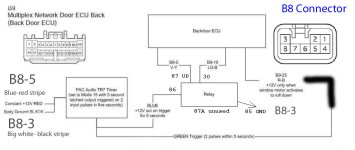
As you look at the ECU it is the connector in the lower right. Mine happens to be blue. You are looking for the blue wire with a red strip which is +12vdc. The white wire with the black stripe is the negative. Look at the last picture in this post.
 
As you look at the ECU it is the connector in the lower right. Mine happens to be blue. You are looking for the blue wire with a red strip which is +12vdc. The white wire with the black stripe is the negative. Look at the last picture in this post.

YES! Thank you very much. I don't know how I missed that. That connector is blue for me too. Looking at the other pictures, then, +12v is at B8-5. Thanks again, I can't wait to try it now.
 
Last edited:
Done!

I have finally completed this mod! Thank you to everyone who helped. Ask questions if you want, I'll try to answer them. I did not use a magnetic switch, because mine didn't work, so all I can tell you is NC stands for normally closed and NO stands for normally open, which is the one you want.

I edited this diagram to show what I did and added some details.

  • Pull the connector from the bottom of the TR-7.
  • Switch the programming switch to on.
  • Connect the black wire to ground
  • Plug the connector back in. Look on the face of the unit where the PAC audio URL is. The LED is under the plastic here.
  • Touch the brown wire to ground 15 times.
  • The TR-7 will flash 15 times (after a couple of seconds)
  • Touch the brown wire to ground 2 times. The TR-7 will flash twice (after a couple of seconds).
  • Touch the brown wire to ground once. (this is the tricky part). The TR-7 will flash quickly. Then after 3 seconds it will do it again. You are waiting until you see a triple flash. It's really kind of like a set of double flashes that happen three times really fast.
  • Touch the brown wire to ground 5 times. The TR-7 will flash 5 times slowly.
  • Wait a bit and the TR-7 will flash rapidly for about 3 seconds. You are done. Put the programming switch back to the off position.

Just to clarify; regarding this seventh bullet point, by tapping the wire once, you are initiating the timer count. What you will see are sets of really quick flashes. The first set (one set of three flashes) means that it is asking for a time interval in minutes. Because we don't want any minutes, we wait until the second set of flashes (two sets of three). This stands for the tens place in seconds, however again we don't have any, so we wait until the third set (three sets of three flashes). This is where you tap the brown wire 5 times to signal 5 seconds. After it repeats your input by flashing 5 times slowly, it will do four sets of three. This means if you mess up, tap once to restart the timer sequence. If you did not mess up, it will flash constantly for 3 seconds. You are done.

That may have been redundant but I thought it might help any one else. I got all of this information from the TR7 flowchart, which I can scan if need be.
 

Attachments

  • rear door remote hack wiring pat copy.jpg
    rear door remote hack wiring pat copy.jpg
    114.2 KB · Views: 929
Last edited:
Thank you for everyone that helped on this mod. I was able to incorporate the magnet switch in the circuit.

The hardest part: programming the trigger. Before connecting the trigger in the rear hatch, I used alligator clips and programmed the trigger directly off the battery terminals. It did keep the program memorized after being disconnected (and left unconnected for months) and worked like a charm after connecting it in place.

Feel free to post any questions you have.
 
Not having luck

Hey has anyone that got this mod to work run into the problem with the TR7 not giving out a 12v output on the blue wire when activated? At this point this is my only problem I'm pretty sure I programmed it correctly with the 5 second timer but I am not getting a 12V output from the blue with to turn the relay on to drive the window up. I have gotten it to work by activating the TR7 with the timer and applying my own 12V source to the relay. Any help will be greatly appreciated.

Thanks,
Leo
 
Hey has anyone that got this mod to work run into the problem with the TR7 not giving out a 12v output on the blue wire when activated? At this point this is my only problem I'm pretty sure I programmed it correctly with the 5 second timer but I am not getting a 12V output from the blue with to turn the relay on to drive the window up. I have gotten it to work by activating the TR7 with the timer and applying my own 12V source to the relay. Any help will be greatly appreciated.

Thanks,
Leo

If the TR7 is programmed correctly, you should be able to hit the green wire with + 12 two times in 5 seconds and then the blue wire will go hot (+12) which activates the relay.

Just disconnect one of the wires from the relay to the ECU for testing so you are not messing with the actual window (but leave power to the relay). You should be able to hear the relay being activated by the TR7. If not, the TR7 isn't programmed correctly or is bad. Most likely the former. It is kind of a pain.
 
Thanks for the reply Asmara I tried putting +12 volts to the green wire by touching it two times to a +12 volt source then the red led in the Tr7 lite up for 5 seconds but still no 12 volt output on the blue wire to make the relay click. I have followed this direction to program my TR7:

Originally Posted by Asmara
Pull the connector from the bottom of the TR-7.
Switch the programming switch to on.
Plug the connector back in. Look on the face of the unit where the PAC audio URL is. The LED is under the plastic here.
Touch the brown wire to ground 15 times.
The TR-7 will flash 15 times (after a couple of seconds)
Touch the brown wire to ground 2 times. The TR-7 will flash twice (after a couple of seconds).
Touch the brown wire to ground once. (this is the tricky part). The TR-7 will flash quickly. Then after 3 seconds it will do it again. You are waiting until you see a triple flash. It's really kind of like a set of double flashes that happen three times really fast.
Touch the brown wire to ground 5 times. The TR-7 will flash 5 times slowly.
Wait a bit and the TR-7 will flash rapidly for about 3 seconds. You are done. Put the programming switch back to the off position.

Just to clarify; regarding this seventh bullet point, by tapping the wire once, you are initiating the timer count. What you will see are sets of really quick flashes. The first set (one set of three flashes) means that it is asking for a time interval in minutes. Because we don't want any minutes, we wait until the second set of flashes (two sets of three). This stands for the tens place in seconds, however again we don't have any, so we wait until the third set (three sets of three flashes). This is where you tap the brown wire 5 times to signal 5 seconds. After it repeats your input by flashing 5 times slowly, it will do four sets of three. This means if you mess up, tap once to restart the timer sequence. If you did not mess up, it will flash constantly for 3 seconds. You are done.
 
Also another thing the only wires used in the TR7 are red for constant 12V, black for ground, Green for the two pulse signal, and blue for 12V output to the relay correct? And the rest are left alone except for the brown which is used for programming.
 
Ok just shipped my TR7 for an exchange hopefully that is all that's wrong with it. Hopefully I'll have better luck with the new one.
 
I just installed my new TR7 and everything works again. I also soldered all of my connections and used liquid electrical tape.

I made an edit to the programing sequence (in bold):

  • Pull the connector from the bottom of the TR-7.
  • Switch the programming switch to on.
  • Connect the black wire to ground
  • Plug the connector back in. Look on the face of the unit where the PAC audio URL is. The LED is under the plastic here.
  • Touch the brown wire to ground 15 times.
  • The TR-7 will flash 15 times (after a couple of seconds)
  • Touch the brown wire to ground 2 times. The TR-7 will flash twice (after a couple of seconds).
  • Touch the brown wire to ground once. (this is the tricky part). The TR-7 will flash quickly. Then after 3 seconds it will do it again. You are waiting until you see a triple flash. It's really kind of like a set of double flashes that happen three times really fast.
  • Touch the brown wire to ground 5 times. The TR-7 will flash 5 times slowly.
  • Wait a bit and the TR-7 will flash rapidly for about 3 seconds. You are done. Put the programming switch back to the off position.
 
[MENTION=47689]dpodo[/MENTION] i am wanting to have a window switch in the inside of the hatch. got any idea on how i should wire it?
 

Forum statistics

Threads
278,312
Messages
3,554,089
Members
248,016
Latest member
Advally Service

Trending content

Back
Top