Snorklesteve
New member
Where do I buy these?


Where do I buy these?

[MENTION=133627]ChucktownRunner[/MENTION]
only way to do a white background with blue needles on your truck would be to solder white LEDs and paint the back of the needles blue. two problems with that though:
1) the needles will be vary hard to see during the day agianst the black faced background. i think this is dangerous and could be an issues for future owners of the truck
2) the needles will not be bright during the night. yes they will be lit up, but the blue will not reflect the white light well.
only way to get different color needles than your background on your cluster is to leave the needles the OEM orange back and install white LEDs for the background. if i ever change a needle color, i remove the OEM orange and paint the back of the needles white. this is very easy to see during the day and also reflects whatever background color you replace well at night.
let me know if you need anything else...

[MENTION=133627]ChucktownRunner[/MENTION]
only way to do a white background with blue needles on your truck would be to solder white LEDs and paint the back of the needles blue. two problems with that though:
1) the needles will be vary hard to see during the day agianst the black faced background. i think this is dangerous and could be an issues for future owners of the truck
2) the needles will not be bright during the night. yes they will be lit up, but the blue will not reflect the white light well.
only way to get different color needles than your background on your cluster is to leave the needles the OEM orange back and install white LEDs for the background. if i ever change a needle color, i remove the OEM orange and paint the back of the needles white. this is very easy to see during the day and also reflects whatever background color you replace well at night.
let me know if you need anything else...
Do you or anyone else know how to fix a fading lcd screen? My display on my JBL head unit has been fading out and has gotten to the point where you can't read it. Also, swapped out my radios LEDs and when I put it back the knobs, led screen, and disc insert leds didn't light up. Maybe I didn't connect the white ribbon correctly when putting it back together? The fading has been going on for a while before the led issue. Thanks!

Do you or anyone else know how to fix a fading lcd screen? My display on my JBL head unit has been fading out and has gotten to the point where you can't read it. Also, swapped out my radios LEDs and when I put it back the knobs, led screen, and disc insert leds didn't light up. Maybe I didn't connect the white ribbon correctly when putting it back together? The fading has been going on for a while before the led issue. Thanks!
Not sure on the LCD screen, sorry.
did you check polarity? did you use a quality iron and not burn up the circuit board? did you properly solder both sides of the LED? did you use the correct replacement LED?
hopefully you can figure it out, especially if you are charging $100 for the cluster swaps!!
Been lurking a while but this is my first post. This forum is an awesome resource for everything T4R! I got inspired to do the LED color swap on my 2005 4Runner Sport V8. Using a lot of info from this forum and some extra tinkering, I've gotten the high brightness neo4's working at full brightness 12V with dimming control. They actually look pretty close to the factory brightness when compared to the factory radio backlight.

As many people found, the neo4 high brightness LED's don't work in the HVAC backlight as it only gets about 6.5-7 volts not 12v. For some reason all the Neo3’s that backlight the knobs and buttons get full 12v but not the backlight for the LCD display itself. I did some tinkering trying to get the Neo4 High brightness LED's working. Many car dimmers that I've seen in the past use a PWM (pulse width modulated) negative side Transistor or Mosfet to control Brightness. I took my Oscilloscope out to the truck and confirmed that it seams to operate that way on my t4r. So the Ground side where the Neo4's plug in is the actual source of the dimming and we just need a straight 12v source for the positive side of the neo4... Make sure to disconnect the positive side of the neo4 from the circuit board contact before you give it 12V otherwise all sorts of bad stuff could happen. I just completely un-wrapped the positive wire out of the neo4 plastic housing and left it sticking straight out the back. Here’s what it looks like:

You can see that on my 05 sport HVAC control, the inner side of the neo4 plugin (ie closer to center of the board) are the positive sides. This may be different for the Limited edition as it is fairly different from the HVAC console on the Sport edition. You need to figure out which side of the Neo4 is positive as they are polarity sensitive. You can figure out which is the positive side of the neo4 using a 9 volt battery or some such. I then soldered a wire from a 12v source to the leads that are now sticking out and are isolated from the circuit board. The 12v source I tracked down and decided to use was pin 14 on the thick ribbon cable that goes from the small board where the main wiring harness plugs in to the board that runs the display.
Here’s a pic:

There are a few other 12v lines that turn on at different times ie always/acc/on etc. Pin 14 turns on at the same time as the factory display did… The High Brightness Neo4’s at 12v give a good level of brightness and give a pretty even backlight when given full power unlike the regular neo4’s. All in all I am very happy with the results. Here’s a picture of my HVAC display half way through the upgrade:

The left side of the display is backlit by a regular neo4 running stock ie just direct swap of the factory bulb. The right side of the display is backlit by a high brightness Neo4 running at 12v. The difference is quite noticeable and actually turns out to be a pretty straight forward upgrade. There are a few things that could go wrong if you’re not comfortable with electronics and hook things up wrong or don’t isolate the LED positive side from the circuit board etc. I hope I have given enough information on the process that I did and have not forgotten any crucial bits.
Next I’ll move on to the dash and steering etc. which all sound fairly straight forward given all the information available here. I solder surface mount parts all the time and feel comfortable doing the chip LED swap... Thanks to all previous posters on this subject for the wealth of information here and hopefully this will in turn help people get a brighter and dimmable HVAC display working on their T4R’s.
Ouch. I can feel the saltiness from here. Definitely not the soldering/polarity/fried circuit board. I have a sneaky suspicion that it's the white connector in the back. I'll check it when I get the time and report back. As for the salt, you guys do the HVAC and all that other cool stuff, so me just offering help to people that only want the cluster shouldn't be a threat. Just trying to help out people who want it done but don't have $200 to pay for it (like myself). High sodium is a killer..!
Do you or anyone else know how to fix a fading lcd screen? My display on my JBL head unit has been fading out and has gotten to the point where you can't read it. Also, swapped out my radios LEDs and when I put it back the knobs, led screen, and disc insert leds didn't light up. Maybe I didn't connect the white ribbon correctly when putting it back together? The fading has been going on for a while before the led issue. Thanks!

Finally got a little time to mess with the radio. The black push down clamps for the white connector were the issue. I didn't see that when you push down one side at a time it pushes the other side out. I'm in the middle of soldering the leds behind the lcd right now. Anyone done this before? I got the LEDs to light up soldering them sideways. Not sure how it will turn out since the other LEDs had the plastic on the side. Wife wanted to go to the movies so I'll post an update when I'm finished.

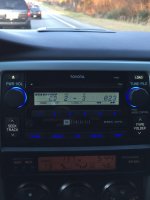
The leds for the lcd screen are soldered on sideways. Here is mine after replacing the leds.

I used this method to get the Neo 4 HP white bulbs in my info display and it worked great. I ended up using the green wire with silver striping for my 12V source. The wire is on the top row, second wire from the passenger side with the white connector oriented the way it is when it is connected to the HVAC. I have a 04 sport and the inner contacts were also the positive side of the board. I just soldered wires to the positive lead on the LEDs, and then taped up the exposed area. I then used a posi-tap to tap into the 12V wire. I feel this is better than using a regular inline tap or soldering since they just screw together and can be unscrewed and screwed back together as many times as you like. I'll post another picture when I get a chance of the 12V wire I used.
http://www.amazon.com/Posi-tap-Connector-20-22-Gauge-Wire/dp/B00389UT3I
Amazon.com: Partsam 4x White T4 Neo Wedge A/c Climate Heater Radio Switch Lamp Led Light Bulbs: Automotive