How to Wire Switches to a Fuse Box
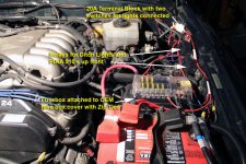
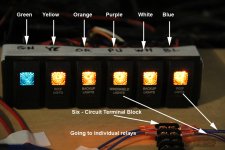
If you look through my build, you'll see that I wired up six switches under a single-din radio on a
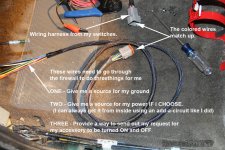
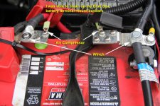
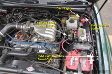
Paranoid Fabrication 2nd Gen Tacoma Switch Plate. To temporarily run my lights, I brought the harness through the firewall and like many before me, mounted my
Blue Sea ST Blade Fuse Block on top of my OEM fuse block. This is a less than ideal location.
I ran my ground for my switches to the
Blue Sea Terminal Mount Busbars and power for the switches was tied into my JB fuse inside the cockpit. My accessories (all two of them) were powered through two 40A Hella Relays via a 15A fuse mounted inside my driver's fender, and ran both lights off of a Blue Sea 20A Terminal Block.
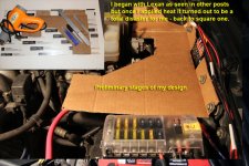
I spent a lot of hours researching the way I wanted to use my available space inside the engine bay and gleaned some great ideas from [MENTION=135677]michaeljtomey[/MENTION] [MENTION=7992]Ripcord[/MENTION] and there was another individual in Tacoma world who used Lexan. (I failed miserably at the Lexan attempt! It was perfect until the heat gun got a hold of it.)
So anyway, here's my "Secondary Power Distribution Assembly."
My own Thoughts as I approached this Project
- I wanted to freely access my OEM fuse box cover and reduce the number of wires running off my battery terminal bus bars.
- I wanted to keep all high voltage components inside the engine bay on that side of the firewall. Relays, Fuse Block, Bus Bars, and terminal blocks.
- If I use a Bus bar I only wanted to use it for my ground wires.
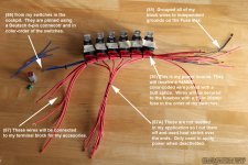
- I didn’t want to loosen up myriads of screws and remove wires if I had to perform any maintenance. I wanted to use the Deutsch connectors where possible and secure as much as possible to the mounting bracket. I have 18 wires I never have to disconnect. I do not have to cut and splice.
- It must be SAFE, clean, and have a professional appearance
- It had to handle additional accessories without ANY modifications. So when I get that 40” or 28” light all I need to do is cut the wires, splice in a color-coded wire and install.
Materials Used
- Stainless steel sheet metal
- Two rubber grommets from Napa
- Deutsch DT Series 6 Pin Connector Kit w/Barrel Style Terminals 16-20 AWG
- 14 awg butt splices
- About twenty ring terminals to fit 18 and 14 awg
- Small Cable ties
- Red and black heat shrink
- Techflex
- Blue Sea ST Blade Fuse Block PN# 5026
- Blue Sea 285 Series Circuit Breaker PN# 7186
- Blue Sea Terminal Block 30A PN# 2506
- Blue Sea Systems DualBus 100A Common BusBars (Optional)
The following photo's will give you an idea of how I built everything
Everything was effective, safe and I'm sure I could have gone forever with the existing setup. I did attach my fuse block to the OEM cover using small zip ties for safety. I've seen folks use hardware there but I didn't want to risk the potential of having a nut come off and shorting my electrical system. I'll replace the cover later on. It was time to upgrade and clean things up a bit.
Using cardboard, I played around with a potential template. Once I was satisfied I went and bought a piece of Lexan and spent hours cutting it out. It was gorgeous...until the heat gun! It looked like a glass blower on drugs got a hold of it. Frustrated it hit the trash - no photo.
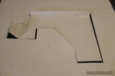
After fine tuning the cardboard and playing around with the components and looking at all the google images I could I finally settled on this pattern utilizing the existing hardware.
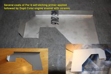
So I brought it to work and grabbed a piece of stainless steel, cut and made the bend. I had top keep the bend to just under 90° to go with the contour of the fender. Using multiple layers of self etching primer by POR 8 and Black Dupli-Color Engine enamel with ceramic I was finished. I still didn't drill any holes yet.
Next I was determined to tuck my relays away somewhere in the drivers fender area. After much consideration I realized that if I bent the mounting tabs up and picked up some very small flush hex-heads with nylocs I could actually mount them on the bracket underneath. First came the grouping of all the wires on the relays. The wires and relays needed to correspond with my color-coded wiring for easy troubleshooting etc...
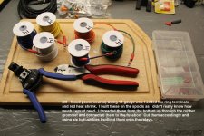
I wasn't sure how long I needed my 14 awg wire to be so I added the ring terminal ends and heat shrink with the wire on the spool. I then threaded the wires up from the bottom through the rubber grommet, connected them to the fuse block and began the process of splicing them into the (30) wires on the relays.
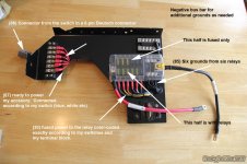
I also decided to utilize independent grounds instead of splicing them all together. If I have a bad relay, it will be much easier to replace in the future. As you can see only half of the fuse block is running through relays. The other half is just fuses for engine bay lighting and other low voltage type lights. I had a dual busbar (pos/neg) but a single ten circuit bus bar would have worked just as well. You can see one additional hole where a sixth relay was originally mounted. I had to move it because it just wouldn't fit very well.
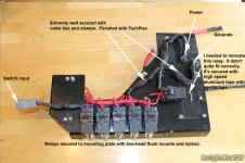
The bottom of the mounting bracket is pretty classy I think. Everything fits extremely well. I did move one relay out of the way and used "speed" tape to secure it to the bracket. The Deutsch connector is the perfect size, relays are very secure. Everything is clamped and extremely tidy. You can see where I cut the 87A wires and used heat shrink over them.
























 was up against the same task as you when looking for the same electrical solution. I've actually made the bracket I use on my rig available on my website. Figured someone else would one day need one and I had wished it was for sale when I made mine hahah. Super clean work man. My only question, by extending the bracket all the way up to the firewall, are you having any issues reaching around and pulling wires through in the future? Hopefully there's enough clearance to get a hand in there!


