Rock Rat's Imperial Jade Mica "Next Adventure" Build

Yea my new tailgating rig! ARB fridge stocked - oh yea! You're still partying over there I'm sure. Not be outdone by you guys, New England gave us one helluva game didn't they! Not a huge fan, but being from NY I had to cheer for them.

Thanks on the switch. Just need a nice way to organize everything under the hood. Nicely made aluminum bracket that goes from the battery to the firewall. I saw one once quite a while ago but haven't been able to find it since. It's not the MJT one. It was full size.

Still having a good time of it. My rich friends (doctors, attorneys) enjoyed being at the game. Their tickets were over $1000 each but on the 40 ten rows up. Must be nice. As in the SB we were able to run twice as many plays as Bama. That will wear down a defense all day.

UW has a great chance next year though USC looks strong. The Rose Bowl this year was great.

Your son still enjoying the Acura? I had a base 03 TL with 118k for $2k get away from me the other week. It needed work but was a one owner dealer serviced.
 
Thanks so much for the pictures Mike! It looks great and gives me a better idea of how these awnings work and how to mount them. If I'm ever up in your neck of the woods I'll be sure to buy you a beer! :beer:
 
How to Wire a Six Switch Paranoid Fabrication Bracket - Con't

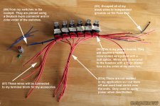
Ok so you know I built a harness for my switches that run from inside the cockpit area out to the firewall. Here's a few pointers:

Splice in a hot wire and a ground wire into your red and black wire ion your connector. Those two wires can stay inside the cockpit area and be used as needed to power up your light switches.

Once you have your harness pulled through the firewall it's time to work on your secondary power supply system to power up your various accessories. I'm going to post up a few more photos but then I need to quit for the night.

IMPORTANT NOTE: Although I changed them for the video, it's best to wire your fuse block and your terminal block in the positions of your switch. My Blue wire should be in position six and the purple wire in position four. Does it really matter? No. If you have OCD - Yes. Might as well do it right the first time.

IMPORTANT: This is an after-fact-note LESSON LEARNED! DO NOT USE BRAIDED WIRE LOOM INSIDE THE ENGINE BAY THROUGH THE GROMMET. YOU WILL EXPERIENCE A LEAK INSIDE YOUR RIG. Please see the repair I made in the following post. Leak Repair This would be the correct way to install your harness. Water coming off your windshield will follow the path of least resistance down your wires and through the firewall.


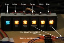
Notice how each switch is labelled for this tutorial only. I'm going to be using the Purple and the Blue wires - switches four and six from left to right. For this tutorial I made two wires with pins for my harness. I'm also using a terminal block for six circuits. It's rated for 20AMP's and will suit my needs just perfectly. Most terminal blocks are on the other side of the firewall. The light blue wires connected to the opposite side of the terminal block go to the relay. This is where all the magic happens. We'll talk about relays and terminal blocks later.
Harness_9.jpg

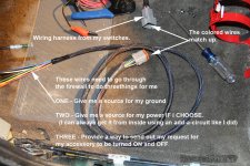
You've seen this picture previously. Keep in mind I still need power and ground for those cool looking daisy chains. I also need to send my switch request somewhere.
Harness_10.jpg


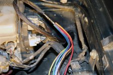
With the other end of the harness inside the engine bay It's time to get organized. I'm going to use my ground from my harness and hook it up to my fuse block. I'm not going to use my red HOT wire as I decided to use the accessory fuse off the junction box
Harness_11.jpg

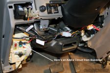
Final picture is a photo of the add-a-circuit. Basically there's an additional wired fuse that taps off the same slot for the accessory circuit breaker but has an independent wire and breaker.
Harness_12.jpg
 

Attachments

  • Harness_9.jpg
    Harness_9.jpg
    88.9 KB · Views: 1,847
  • Harness_10.jpg
    Harness_10.jpg
    140.9 KB · Views: 1,632
  • Harness_11.jpg
    Harness_11.jpg
    137.2 KB · Views: 1,573
  • Harness_12.jpg
    Harness_12.jpg
    110.2 KB · Views: 1,705
Last edited:
I just read through the rest of this thread, you have been busy!

Excellent build, very well written up, and true attention to detail, just what I like!

It amused me that you took ages to do your spindles.

I got mine 10 months ago. -Started them last week. :heh:
 
How to Wire Switches to a Fuse Box

If you look through my build, you'll see that I wired up six switches under a single-din radio on a Paranoid Fabrication 2nd Gen Tacoma Switch Plate. To temporarily run my lights, I brought the harness through the firewall and like many before me, mounted my Blue Sea ST Blade Fuse Block on top of my OEM fuse block. This is a less than ideal location.

I ran my ground for my switches to the Blue Sea Terminal Mount Busbars and power for the switches was tied into my JB fuse inside the cockpit. My accessories (all two of them) were powered through two 40A Hella Relays via a 15A fuse mounted inside my driver's fender, and ran both lights off of a Blue Sea 20A Terminal Block.

I spent a lot of hours researching the way I wanted to use my available space inside the engine bay and gleaned some great ideas from [MENTION=135677]michaeljtomey[/MENTION] [MENTION=7992]Ripcord[/MENTION] and there was another individual in Tacoma world who used Lexan. (I failed miserably at the Lexan attempt! It was perfect until the heat gun got a hold of it.)

So anyway, here's my "Secondary Power Distribution Assembly."

My own Thoughts as I approached this Project
  • I wanted to freely access my OEM fuse box cover and reduce the number of wires running off my battery terminal bus bars.
  • I wanted to keep all high voltage components inside the engine bay on that side of the firewall. Relays, Fuse Block, Bus Bars, and terminal blocks.
  • If I use a Bus bar I only wanted to use it for my ground wires.
  • I didn’t want to loosen up myriads of screws and remove wires if I had to perform any maintenance. I wanted to use the Deutsch connectors where possible and secure as much as possible to the mounting bracket. I have 18 wires I never have to disconnect. I do not have to cut and splice.
  • It must be SAFE, clean, and have a professional appearance
  • It had to handle additional accessories without ANY modifications. So when I get that 40” or 28” light all I need to do is cut the wires, splice in a color-coded wire and install.
Materials Used
  • Stainless steel sheet metal
  • Two rubber grommets from Napa
  • Deutsch DT Series 6 Pin Connector Kit w/Barrel Style Terminals 16-20 AWG
  • 14 awg butt splices
  • About twenty ring terminals to fit 18 and 14 awg
  • Small Cable ties
  • Red and black heat shrink
  • Techflex
  • Blue Sea ST Blade Fuse Block PN# 5026
  • Blue Sea 285 Series Circuit Breaker PN# 7186
  • Blue Sea Terminal Block 30A PN# 2506
  • Blue Sea Systems DualBus 100A Common BusBars (Optional)

The following photo's will give you an idea of how I built everything


Everything was effective, safe and I'm sure I could have gone forever with the existing setup. I did attach my fuse block to the OEM cover using small zip ties for safety. I've seen folks use hardware there but I didn't want to risk the potential of having a nut come off and shorting my electrical system. I'll replace the cover later on. It was time to upgrade and clean things up a bit.
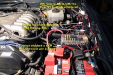
Fusebox_1.jpg


Using cardboard, I played around with a potential template. Once I was satisfied I went and bought a piece of Lexan and spent hours cutting it out. It was gorgeous...until the heat gun! It looked like a glass blower on drugs got a hold of it. Frustrated it hit the trash - no photo.
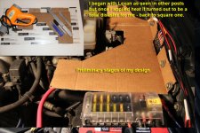
Fusebox_2.jpg

After fine tuning the cardboard and playing around with the components and looking at all the google images I could I finally settled on this pattern utilizing the existing hardware.
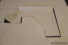
Fusebox_3.jpg

So I brought it to work and grabbed a piece of stainless steel, cut and made the bend. I had top keep the bend to just under 90° to go with the contour of the fender. Using multiple layers of self etching primer by POR 8 and Black Dupli-Color Engine enamel with ceramic I was finished. I still didn't drill any holes yet.
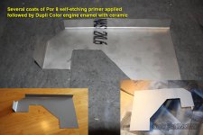
Fusebox_4.jpg

Next I was determined to tuck my relays away somewhere in the drivers fender area. After much consideration I realized that if I bent the mounting tabs up and picked up some very small flush hex-heads with nylocs I could actually mount them on the bracket underneath. First came the grouping of all the wires on the relays. The wires and relays needed to correspond with my color-coded wiring for easy troubleshooting etc...
Fusebox_5.jpg

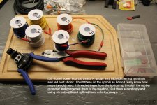
I wasn't sure how long I needed my 14 awg wire to be so I added the ring terminal ends and heat shrink with the wire on the spool. I then threaded the wires up from the bottom through the rubber grommet, connected them to the fuse block and began the process of splicing them into the (30) wires on the relays.
Fusebox_6.jpg

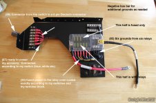
I also decided to utilize independent grounds instead of splicing them all together. If I have a bad relay, it will be much easier to replace in the future. As you can see only half of the fuse block is running through relays. The other half is just fuses for engine bay lighting and other low voltage type lights. I had a dual busbar (pos/neg) but a single ten circuit bus bar would have worked just as well. You can see one additional hole where a sixth relay was originally mounted. I had to move it because it just wouldn't fit very well.
Fusebox_7.jpg

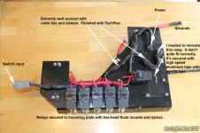
The bottom of the mounting bracket is pretty classy I think. Everything fits extremely well. I did move one relay out of the way and used "speed" tape to secure it to the bracket. The Deutsch connector is the perfect size, relays are very secure. Everything is clamped and extremely tidy. You can see where I cut the 87A wires and used heat shrink over them.
Fusebox_8.jpg
 

Attachments

  • Fusebox_1.jpg
    Fusebox_1.jpg
    143 KB · Views: 1,418
  • Fusebox_2.jpg
    Fusebox_2.jpg
    135.6 KB · Views: 1,297
  • Fusebox_3.jpg
    Fusebox_3.jpg
    36.7 KB · Views: 1,154
  • Fusebox_4.jpg
    Fusebox_4.jpg
    100.3 KB · Views: 1,356
  • Fusebox_5.jpg
    Fusebox_5.jpg
    135.6 KB · Views: 1,553
  • Fusebox_6.jpg
    Fusebox_6.jpg
    134.8 KB · Views: 1,273
  • Fusebox_7.jpg
    Fusebox_7.jpg
    116.6 KB · Views: 1,907
  • Fusebox_8.jpg
    Fusebox_8.jpg
    120.3 KB · Views: 1,502
Last edited:
Dam you people without charcoal canisters in the engine bay. lol I just got done pretty much the same wiring on my 97. That charcoal canister made me do things much differently. In the end it worked out very well and ended up pretty clean. I did use bolts to mount my Blue Sea box to my fuse box lid though. I used lock washers on it so I'm pretty sure it won't be going anywhere. As added insurance I put a tiny bit of silicone under the pan head bolt on the inside of the fuse box lid.

The trucks looking really good man.
 
How to Wire Switches to a Fuse Box - Finale

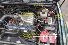
The final photos give you an idea of the room it takes and how much more tidy the engine bay looks.

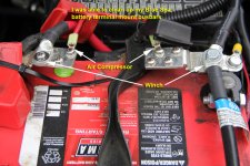
The only things I have running off my battery are my winch and my air compressor.

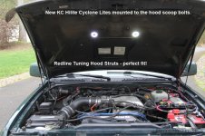
During my installation my RedLine Tuning hood struts arrived so I was left with no option. I had to install them first. AWESOME MOD!!! Because of the struts, I needed to cut a small "V" in my mounting bracket. Nothing a dremel couldn't fix.

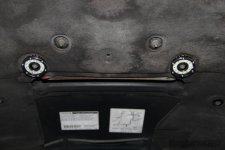
I also picked up two "Cyclone LED Light - Black - PN#1350" for the engine bay. The KC website shows 511 lumens each. They mount PERFECTLY on the hardware used for the hood scoop. At 400 lumens each, they provide plenty of light in the engine bay. I was able to run the wires through the insulation and wire them to a PIAA switch I no longer needed. Another great inexpensive mod. I have no problem with the wire hanging down where it does. My other option is to relocate the switch closer to the firewall.

It's pretty neat to just hit your switch for light under the hood and not having a hood support rod in the way.

Nice tidied up terminal mounts.
Fusebox_9.jpg


The new Fuse Block mount fits perfectly in a 2001. Plenty of room to work around it and I still have the ability to remove it without cutting wires or undoing a bazzilion screws.
Fusebox_10.jpg

KC Hilites are awesome. What took me so long?
KC Hilites Engine Bay.jpg

KC Hilites Engine Bay_2.jpg
 

Attachments

  • Fusebox_9.jpg
    Fusebox_9.jpg
    141.3 KB · Views: 1,171
  • Fusebox_10.jpg
    Fusebox_10.jpg
    144.3 KB · Views: 1,224
  • KC Hilites Engine Bay.jpg
    KC Hilites Engine Bay.jpg
    80.2 KB · Views: 1,170
  • KC Hilites Engine Bay_2.jpg
    KC Hilites Engine Bay_2.jpg
    131.6 KB · Views: 987
Last edited:
Dam you people without charcoal canisters in the engine bay. lol I just got done pretty much the same wiring on my 97. That charcoal canister made me do things much differently. In the end it worked out very well and ended up pretty clean. I did use bolts to mount my Blue Sea box to my fuse box lid though. I used lock washers on it so I'm pretty sure it won't be going anywhere. As added insurance I put a tiny bit of silicone under the pan head bolt on the inside of the fuse box lid.

The trucks looking really good man.

Thanks. Yea, it's nice having all that room to play around with. I'm not sure what your options are with the canisters in the way. I think the way you have it bolted to the OEM cover is the only way to go. The brackets that MJT makes look like they would be a good solution as they slide in from the top down. The other option which is a good option as well is the Bussman RTM fuse box. I'm going with either that or an S-Pod with my next rig.
 
Looks great man! I have a 2000 IJM Highlander/Sport. Just getting all the maintenance up to date then I can start on mods. Great thread.

Justin
 
That's some pretty impressive electrical work Mike. I dig it. I would like to add something like that down the road to better serve the needs of winch, lights, and compressor. I like the idea is have seen others have incorporated to have a physical kill switch for power to winch. Time to start researching.
 
Great work!! Glad I could be of inspiration :D was up against the same task as you when looking for the same electrical solution. I've actually made the bracket I use on my rig available on my website. Figured someone else would one day need one and I had wished it was for sale when I made mine hahah. Super clean work man. My only question, by extending the bracket all the way up to the firewall, are you having any issues reaching around and pulling wires through in the future? Hopefully there's enough clearance to get a hand in there!

http://4runnergrille.com/shop/96-02-fuse-block-bracket/
 
Looks great man! I have a 2000 IJM Highlander/Sport. Just getting all the maintenance up to date then I can start on mods. Great thread.

Justin

Thanks Justin. Looks like you have your priorities in perspective. I look forward to seeing your progress.

That is art :first:

Thanks! Didn't expect to get some "hardware" for the trophy case - first place at that!

That's some pretty impressive electrical work Mike. I dig it. I would like to add something like that down the road to better serve the needs of winch, lights, and compressor. I like the idea is have seen others have incorporated to have a physical kill switch for power to winch. Time to start researching.

Thanks man I appreciate the kudos. When you're ready I'll gladly provide assistance. Hmmm a kill switch for the winch. I'll have to research that one a bit. I like the idea.

Great work!! Glad I could be of inspiration :D was up against the same task as you when looking for the same electrical solution. I've actually made the bracket I use on my rig available on my website. Figured someone else would one day need one and I had wished it was for sale when I made mine hahah. Super clean work man. My only question, by extending the bracket all the way up to the firewall, are you having any issues reaching around and pulling wires through in the future? Hopefully there's enough clearance to get a hand in there!

http://4runnergrille.com/shop/96-02-fuse-block-bracket/

I saw yours in a group buy last year and a few others that have installed them. I almost jumped on it but it just wasn't exactly what I was looking for only because I have so much room in the 01. I didn't want to limit myself if you know what I mean. Quality bracket though!! It's great of you to offer that up to folks since not everyone has access to the equipment needed to make one on their own.

I can actually reach under there almost all the way to the corner with my left arm without too much of a problem. My only thought on that was I have four connections left on that terminal block. The plan is for a 40" E series Rigid, two rear floods and side floods and a 28" E Series Rigid to replace the PIAA's Most, if not all of those wires will be routed through the wire loom on top of the bracket. If I have to go under the bracket, I would loosen it up anyway to secure the wires. I guess the test of time will tell. I like your thought process.
 
Last edited:
Hmmm a kill switch for the winch. I'll have to research that one a bit. I like the idea.

I picked up this disconnect from amazon to use with my winch.

350Amp Disconnect

I haven't installed it yet but the plan is to pull the fan shroud and mount it there. The 350A rating was as big as I could find without going to the realm of way to expensive and bulky. I'm hoping it will be enough but most of my research suggests under heavy load my 12000 Engo could go higher than that rating. For now I just put a top post positive terminal on with a wing nut. The hot for the winch is coiled in front of the battery. So undo wing nut, hook up winch, put wing nut back on. lol
 
I like it [MENTION=116467]Rock_Rat[/MENTION]. Very similar to my start of the build.

That disconnect is okay, but please don't try to take 350Amps through it, lol.

I have seen a lot of dual battery threads and like [MENTION=116467]Rock_Rat[/MENTION], engine I have no room for a second battery and been playing with ideas of where to go. ...

Love the build we should meet up sometime, but need to wait 3 weeks for me to finish the last two projects haha. :)
 
Ok so you know I built a harness for my switches that run from inside the cockpit area out to the firewall. Here's a few pointers:

Splice in a hot wire and a ground wire into your red and black wire ion your connector. Those two wires can stay inside the cockpit area and be used as needed to power up your light switches.

Once you have your harness pulled through the firewall it's time to work on your secondary power supply system to power up your various accessories. I'm going to post up a few more photos but then I need to quit for the night.

IMPORTANT NOTE: Although I changed them for the video, it's best to wire your fuse block and your terminal block in the positions of your switch. My Blue wire should be in position six and the purple wire in position four. Does it really matter? No. If you have OCD - Yes. Might as well do it right the first time.


Notice how each switch is labelled for this tutorial only. I'm going to be using the Purple and the Blue wires - switches four and six from left to right. For this tutorial I made two wires with pins for my harness. I'm also using a terminal block for six circuits. It's rated for 20AMP's and will suit my needs just perfectly. Most terminal blocks are on the other side of the firewall. The light blue wires connected to the opposite side of the terminal block go to the relay. This is where all the magic happens. We'll talk about relays and terminal blocks later.
View attachment 238980

You've seen this picture previously. Keep in mind I still need power and ground for those cool looking daisy chains. I also need to send my switch request somewhere.
View attachment 238981


With the other end of the harness inside the engine bay It's time to get organized. I'm going to use my ground from my harness and hook it up to my fuse block. I'm not going to use my red HOT wire as I decided to use the accessory fuse off the junction box
View attachment 238982

Final picture is a photo of the add-a-circuit. Basically there's an additional wired fuse that taps off the same slot for the accessory circuit breaker but has an independent wire and breaker.
View attachment 238983

Awesome work. From experience. I have the same wire loom like you have. That braided sleeve. And mine to goes trough that grommet. Becareful for a wet carpet under your feet. Water will go down the windshield. Drip "directly" on top of those wires and travel down the wire inside the truck. Because that wire look, even though it's awesome. It doesn't seal around the grommet properly. Because the wire is under it. And the wire loom is open, as in has pores. So it will get onto the wire loom and travel down the wire. Just becareful. I fixed mine with A LOT LF RTV. LIKE A LOT. to seal the wire loom
 
Thanks. Yea, it's nice having all that room to play around with. I'm not sure what your options are with the canisters in the way. I think the way you have it bolted to the OEM cover is the only way to go. The brackets that MJT makes look like they would be a good solution as they slide in from the top down. The other option which is a good option as well is the Bussman RTM fuse box. I'm going with either that or an S-Pod with my next rig.

I installed a aux fuse box under the rear seat where the OEM jack goes. Ran 5 wires to the back and 5 to the front. I just tap into them and that's all. This was my only solution. For installin bussmann 10relay box
 

Members online

Forum statistics

Threads
278,317
Messages
3,554,129
Members
248,016
Latest member
Advally Service

Trending content

Back
Top