Ruby Tuesday - rad4runner's Mods and Restoration

RAD4Runner

Senior Member
Well... these are not hard-core restoration write-ups, strictly-speaking, but mostly enhancements, mods, fixes...

 
Register to hide this ad
Solution For "Click-Only" Start Issue

This is the clean, simple, robust fix for the starting (cranking) circuit wiring flaw explained here. This mod fixed my "click-only" starting issue. No additional or replacement parts, except for wire and a kill switch.

THIS APPLIES TO MODELS WITH STARTER RELAY, SUCH AS:
Those made from May 1986 and later.
Those made earlier than May Like richiegrich's Feb, and KidV's do not have starter relay.

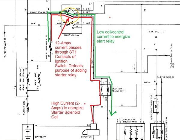
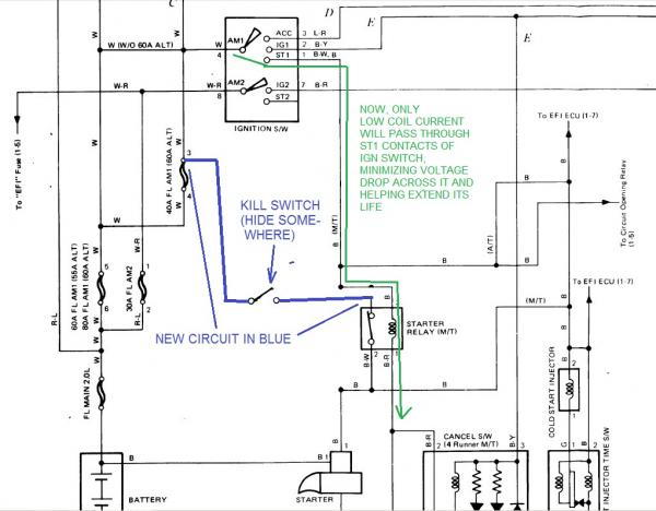
Schematic below shows that high current (12-Amps) to energize starter solenoid passes through ST1 contacts of ignition switch. This puts unnecessary stress on switch contacts, cause pitting, high resistance, too much voltage drop (solenoid not getting enough voltage), and defeats purpose of adding the relay in the first place.

rad4runner-albums-starting+circuit-picture26165-01-start-relay-current-path.jpg


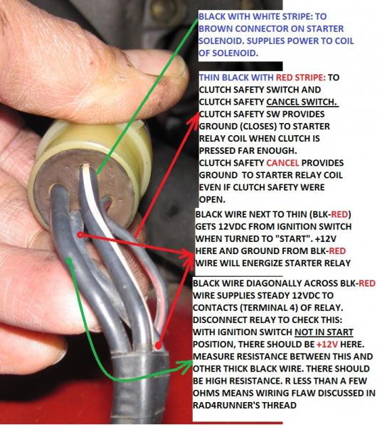
To verify if your stock wiring has this flaw:
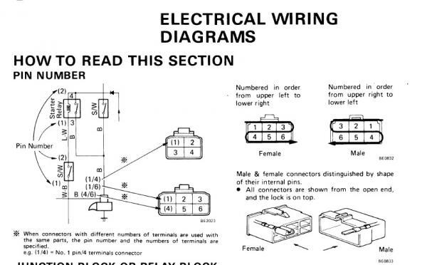
rad4runner-albums-starting+circuit-picture26337-pin-outs-starter-relay-connector.jpg


To correct:
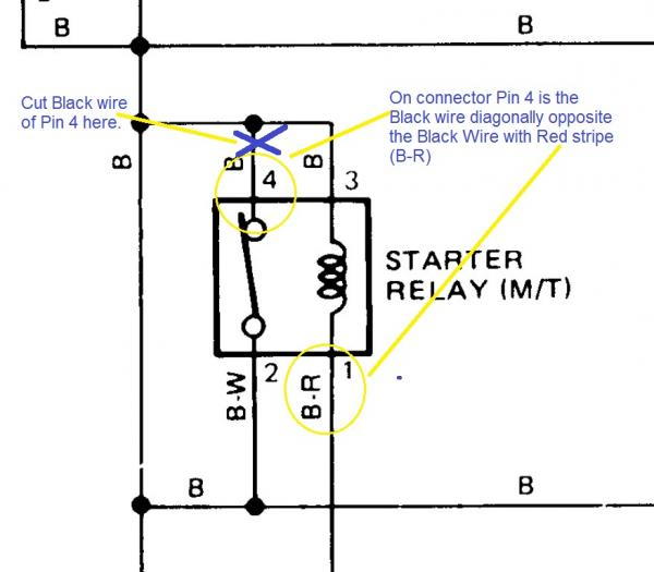
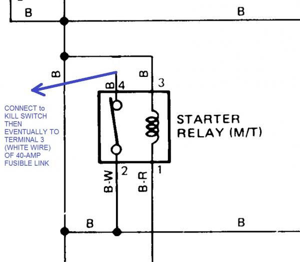
Cut wire to pin 4 of starter relay here:

rad4runner-albums-starting+circuit-picture26166-02-start-relay-cut-pin4.jpg


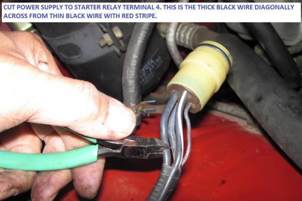
Picture here:

rad4runner-albums-starting+circuit-picture26329-start-relayconnector-snip-term-4.jpg

Insulate end on harness. This will not connect to anything anymore.

It should look like this now.

rad4runner-albums-starting+circuit-picture26167-03-move-pin4-start-relay.jpg


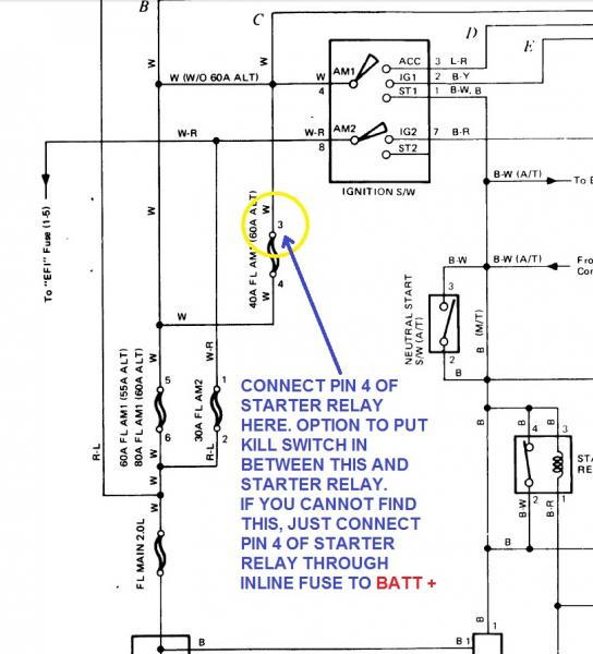
To find Pin3, look for terminal of 40-Amp fuse that connects to 80A Fusible link. This is terminal 4. Terminal 3 is the opposite terminal. To verify that you have the right Pin3 of FL, measure voltage there. With 40-Amp fuse installed, you should get 12V. Remove 40-amp fuse, you should get no voltage.
Connect (crimp or crimp PLUS solder) wire from Start relay Pin 4 to Terminal 3 of FL.
rad4runner-albums-starting+circuit-picture28200-tap-power-start-relay-contact-here.jpg


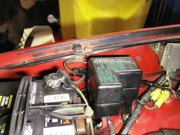
Fusible Link is in this fuse block:
rad4runner-albums-battery+wiring-picture26040-body-ground_zoom-out.jpg


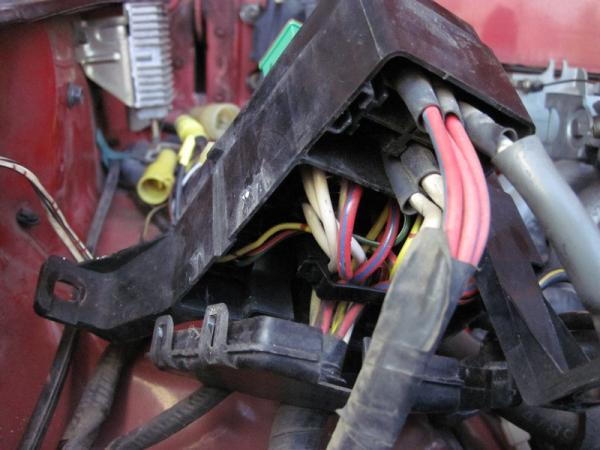
Terminal 3 is accessible from bottom.
rad4runner-albums-battery+wiring-picture25266-swerks-mystery-white-wire.jpg

IIRC, this picture shows Terminal 3 removed so I can tap into it.
Verify it is Pin3, such that when you remove FL you do not get +12V, and you get +12V when FL is re-installed.

When you make a tap, make sure you have both mechanical & electrical integrity (i.e., crimp OR wrap around existing wire then solder).

It would be nice to insert a kill switch in wire between FL and start relay. Hide it and don't post where you put it here (duh!). Bonus is that kill switch will interrupt power in the extremely rare case that starter relay contacts get welded in closed position. Final circuit should look like this:

rad4runner-albums-starting+circuit-picture26169-05-start-relay-fix-final-circuit.jpg
 
Last edited:
Alternator Upgrade To 90-Amp Stator >> What's This Part?

I recently had AES in San Diego install a stock body alternator with stator upgraded to 90-Amp one. Before I add any auxiliary equipment (lights/audio system), I would upgrade my wiring.

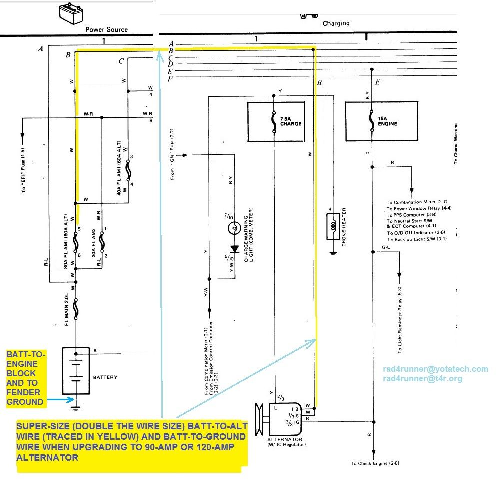
One important part of of a robust upgrade would be to super-size (double to be safe) effective wire thicknesses of the following:
  • Alternator-to-battery positive wire (traced in yellow on schematic below),
  • Battery-to-engine block ground wire (this is where it connects to alternator ground, and
  • Battery to fender ground (this is where many accessories, lights, ignition, etc) systems return.

Any additional circuit should be tapped off the upgraded alt-to-batt wire and properly fused. This way alt and battery will provide current / aid each other depending on demand, via safe paths - proper wire capacity, proper auxiliary fuses and stock fuses that are not bypassed.

Charging_Alt_Batt_01_zpsf1a3ec83.jpg~original


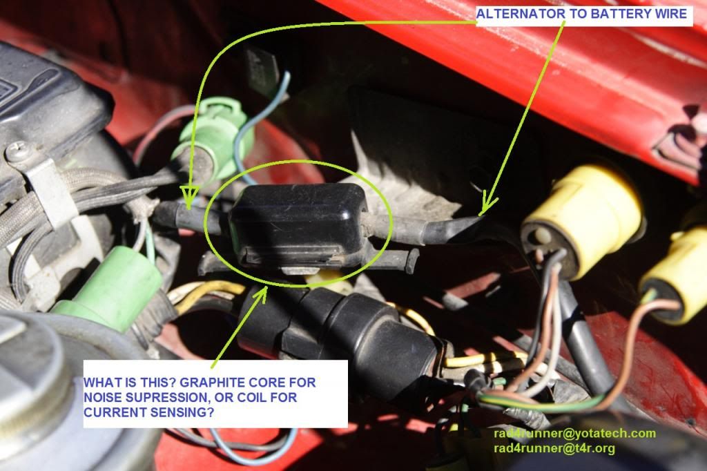
I would simply put another wire in parallel with existing alt-to-batt wire. However, there is a cube looking thing around the alt-to-batt wire. It does not show in schematic above. Could this simply be a ferrite noise suppression core? It could be a current sensing coil, but I do not see any wires connected to it. Does anyone now what it is?
001_Graphite_Core_Maybe-Copy_zps6b1d7775.jpg~original


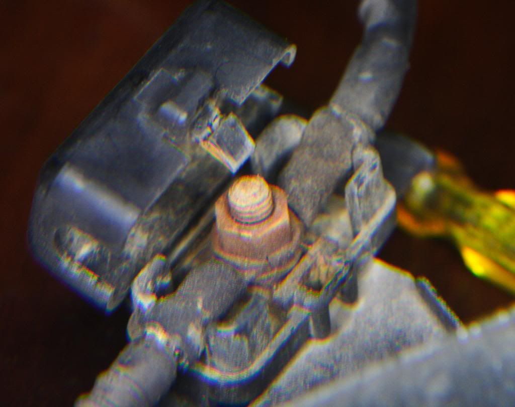
Guys, I finally opened it up. It's just a junction point. No foreseen use at all, and is another potential point of failure from corrosion or loose nut & bolt. I will eliminate when I upgrade my alt-to-battery wire.

001_Just_Junction_Point_zpsa274310f.jpg~original
 
Last edited:
Wait, who's choking ferrets now?

Any additional circuit should be tapped off the upgraded alt-to-batt wire and properly fused. This way alt and battery will provide current / aid each other depending on demand, via safe paths - proper wire capacity, proper auxiliary fuses and stock fuses that are not bypassed.

Can you rephrase that for us slow children? If I drop in an auxiliary fuse block, you're saying don't feed it straight off the positive battery terminal?
 
Last edited:
Kinda looks like a ferrite choke.

Oh yes, I meant "Ferrite" Core, 'cause nothing's wired to it. Thanks, 92-SR5

Wait, who's choking ferrets now?
I meant Ferret - LOL!

Can you rephrase that for us slow children? If I drop in an auxiliary fuse block, you're saying don't feed it straight off the positive battery terminal?
Correct, KidV. Worst-case scenario (maybe remote possibility but): If there is demand for current up to capacity of upgraded alternator, the stock alt-to-batt wire will not handle the 120-Amperes or 90-amperes from alt.

That's why I want to super-size that wire by wiring one of same size in parallel. If anyone has that wire /sees that in a junkyard, please advise how much it would cost including shipping.
Else, I'll just get new wire of thicker gauge and replace stock one.
 
Relocate Rear Window & Wiper Switch

I relocated my console switches to the dash because they are in a retarded location subject to spilled drinks, AND in order to make way for future cup holder. Finally got the chance to post it here.

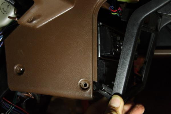
To remove radio section faceplate, remove this front screw, left & right sides:
rad4runner-albums-console+switch+relocation+-+cup+holder+mod-picture26606-001-unscrew.jpg


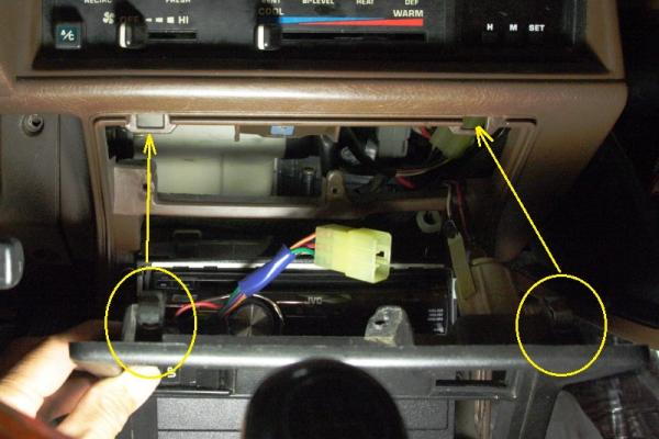
Pop these tabs out;
rad4runner-albums-console+switch+relocation+-+cup+holder+mod-picture26607-002-tabs.jpg


Work area is under Driver's Seat:
Before:
rad4runner-albums-console+switch+relocation+-+cup+holder+mod-picture26630-009.jpg


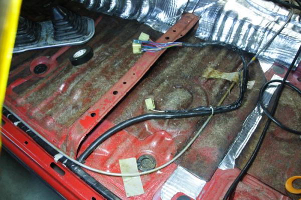
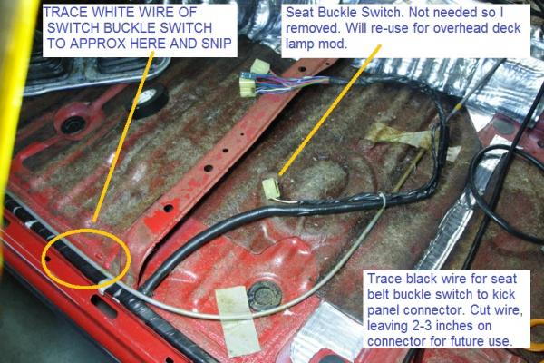
I do not need seat buckle switch so I removed and will re-use as connectors for my overhead deck lamp for when top has to come off. If you want to keep as much wire on the connector as possible, trace white one where it splices into others along threshold. Trace black wire all the way back to kick panel connector. Cut but leave 2-3 inches on latter connector for future use.
rad4runner-albums-console+switch+relocation+-+cup+holder+mod-picture26632-009.jpg
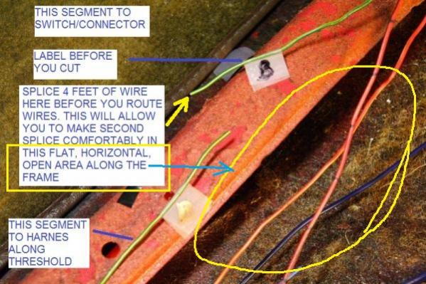
Label each wire before cutting. Make sure both sides have labels :).
Splice approx 4 feet of additional wire to each orig. wire to leave you room to work with. Splice on segment of wire on connector/switch side.
rad4runner-albums-console+switch+relocation+-+cup+holder+mod-picture26633-user101367-pic26609-1351102116.jpg


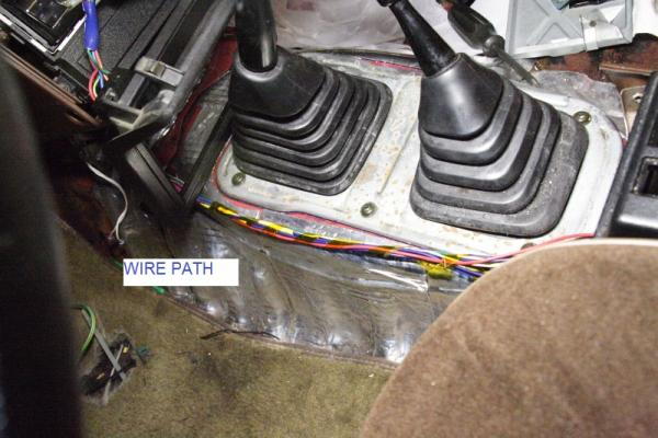
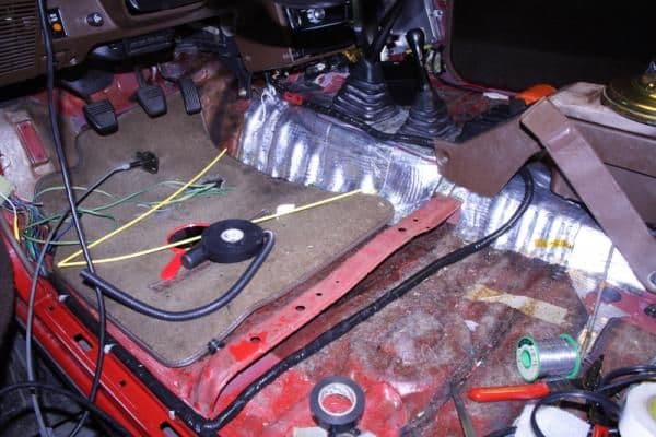
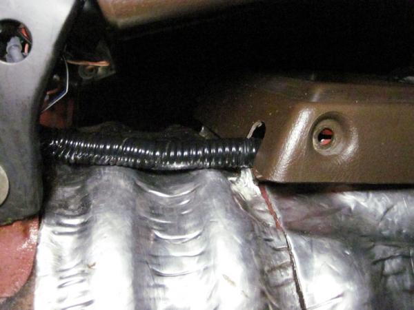
I ran harness along here:
rad4runner-albums-console+switch+relocation+-+cup+holder+mod-picture26612-008-wire-path.jpg


rad4runner-albums-console+switch+relocation+-+cup+holder+mod-picture26610-006-route-wire.jpg


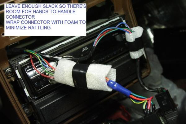
Route wires so you have enough slack to handle connectors when removing or installing face plate.
rad4runner-albums-console+switch+relocation+-+cup+holder+mod-picture26611-007-slack-foam.jpg


New Harness Routing.
3/8-inch conduit tube is too thin. Better to use 0.5-inch diameter one.
rad4runner-albums-console+switch+relocation+-+cup+holder+mod-picture26613-009-harness.jpg


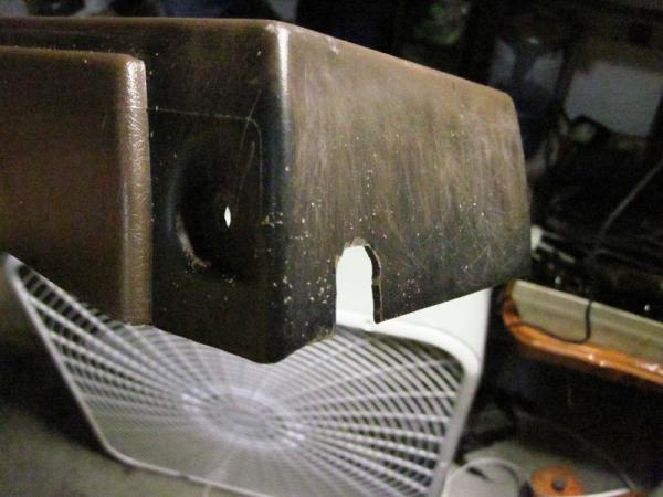
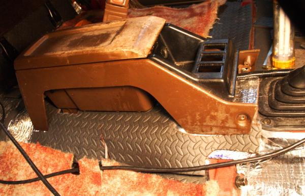
Notch Transmission Cover To Clear Harness:
Front
rad4runner-albums-console+switch+relocation+-+cup+holder+mod-picture26638-002.jpg


Rear
rad4runner-albums-console+switch+relocation+-+cup+holder+mod-picture26637-001.jpg


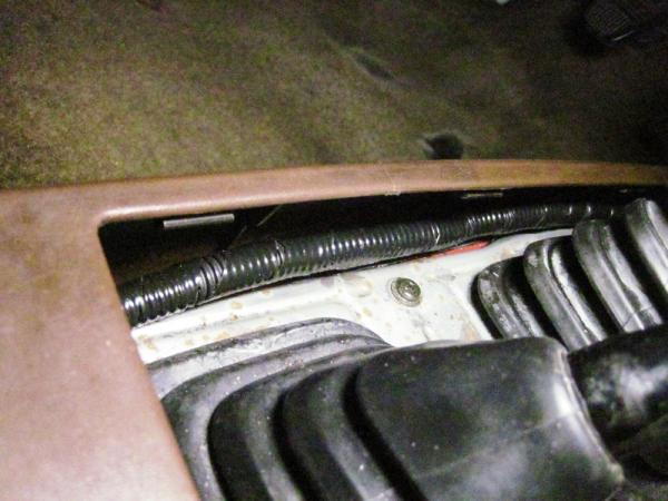
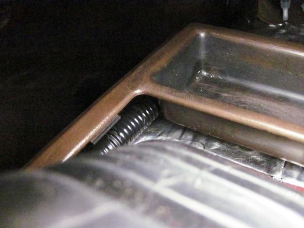
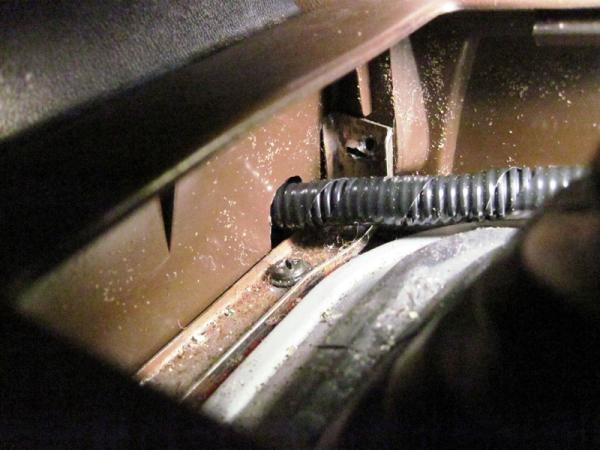
Checking Clearances:
Make harness hug the plastic so repeated shifting does not disturb it.
rad4runner-albums-console+switch+relocation+-+cup+holder+mod-picture26642-008.jpg


rad4runner-albums-console+switch+relocation+-+cup+holder+mod-picture26640-004.jpg


Rear Clearance:
rad4runner-albums-console+switch+relocation+-+cup+holder+mod-picture26639-003.jpg


Front Clearance:
rad4runner-albums-console+switch+relocation+-+cup+holder+mod-picture26641-006.jpg


Final Product:

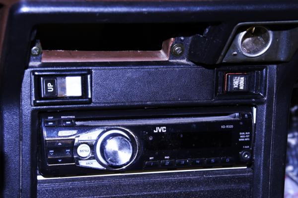
Window switches here.
rad4runner-albums-console+switch+relocation+-+cup+holder+mod-picture26614-100-window-switches.jpg


Where lock switch went, there is already a capped opening- just pop cap off. Fits standard 4Runner switch profile.
Where Up/Down switch is there was cut-out waiting to be cut. Just cut tabs off and clean up. Save this tab for template for additional switch locations. To mount a third switch between the 2, use tab above as template. Make sure you make opening slightly smaller than the template. I used tiny dill bit to outline the cut, finish cut with thin soldering tip, and cleaned up with needle file.

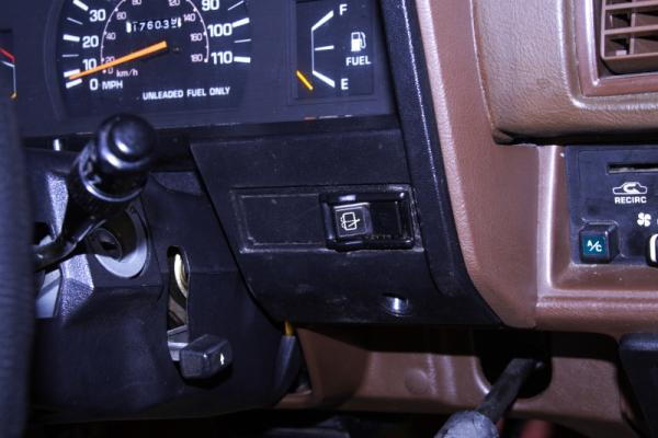
Wiper Switch Forward of windshield wiper lever. I used tab above as template. I used tiny dill bit to outline the cut, finish cut with thin soldering tip, and cleaned up with needle file.

If you have cruise control switch here (forward of wiper stalk), mount wiper switch together with window switches above the radio.
rad4runner-albums-console+switch+relocation+-+cup+holder+mod-picture26615-101-wiper-switch.jpg


Available Real Estate: My Console Begging Me to Mod Her for a Cupholder =D

rad4runner-albums-console+switch+relocation+-+cup+holder+mod-picture27282-cupholder-please.jpg


Next Step Cup Holder Mod (Work in Progress)
 
Last edited:
Headlight Circuit Retrofit

Stock:
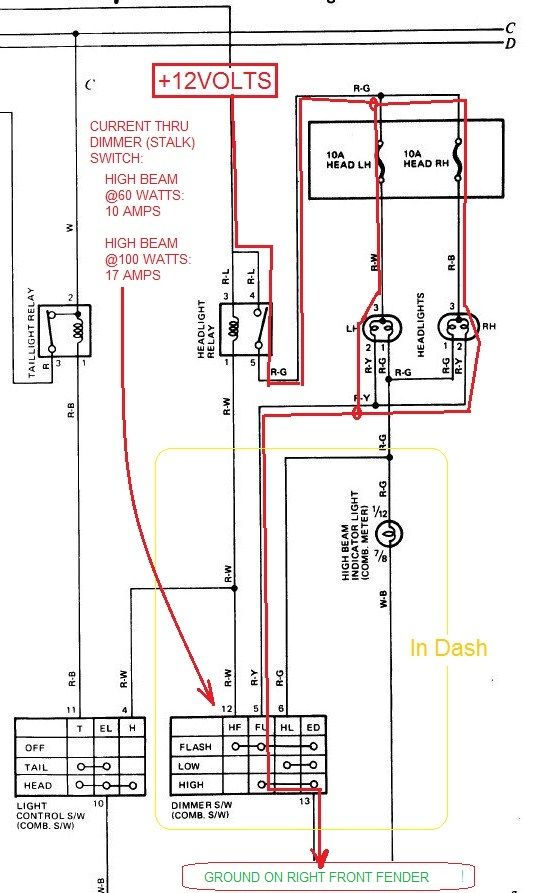
  • Dimmer (combo) stalk switch contacts carry high current for headlights.
  • Wires are thin.
  • Ground circuit goes on thin wires (AWG 18/20?), from bulbs, to cabin, to dash to dimmer switch, back to engine compartment to ground inside passenger side fender (exactly a convoluted path as 4Crawler describes it), causing a lot of resistance, a lot of voltage drop (15% of battery voltage measured in high beam) and reducing voltage that ends up across the bulbs.
  • High current (traced in red; 10 Amps on 60-watt high beam, 17 Amps on 100-watt high beams) through dimmer switch contacts will shorten contact life.
Headlight_ONLY_Current-Red.jpg~original


Shortcuts:
Bulb upgrades increase light output but only mask the problem, above conditions still exist.
Using 55/100 bulbs makes issue with higher current (17 Amps in High beam) through dimmer-switch worse.

H4 conversion harness:
Conversion harness is a a robust, clean solution IF made well (where are they made? =D).
However, I want my mods uncluttered, simple, with minimal additional parts. So here goes (Not for the filum-phobic - LOL!):

As of 1205 Hrs, 01Apr2013:
  • Used only one additional part, a 5-pin relay, plus solder & wiring supplies.
  • Uses existing headlight fuses
  • Upgraded to thicker 12AWG wires, from fuses to ground
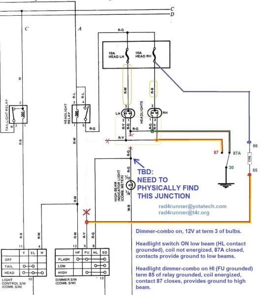
  • Ground path goes directly from bulb to relay to fender ground, minimizing voltage drops.
  • Relay carries headlight current, helping extend dimmer switch life.
  • Using normally-closed contact 87A replicates stock circuit for low beam. Even IF relay fails (no power, no ground, or coil open), low beam will still work.

Schematic is here (Slumming with MS Paint 'cause I lost Auto CAD license with upgrade to Windows 7 :(] :
rad4runner-albums-lighting+schematics++pics-picture29635-20130331-headlight-rewire-ground-path-working-drawing.jpg~original


Voltage Drop Comparisons:
Expressed as % of battery voltage because batt voltage not exactly same before and after retrofit.
With Sealed Beam & Stock Wiring, Engine off
Low Beam:
Batt: 12.05V, Bulb 11.15V
Voltage drop in wiring: 0.9V
volt drop = 7.5%
High Beam:
Batt 11.94, bulb 10.07
Volt drop: 15.7%​

After Retrofit:
Low Beam:
Batt: 12.31V, Bulb 12.11V
Volt Drop: 0.2 = 1.6% of Battery voltage
High Beam:
Batt: 12.24V, bulb 11.78V
Voltage drop: =0.46V = 3.75% of battery voltage

Still To Do:
High beam indicator circuit TBD after I find junction as noted on schematic.
I could connect positive side of high-beam indicator to 87a, but that would still put some current through dimmer-switch contacts. Looking for better solution as soon as I physically find the junction of HL contact of dimmer switch and positive side of high-beam indicator.

keyword search H4 conversion, H4 convert, headlight retrofit, headlightretrofit
 
Last edited:
Divide & Conquer!

Splitting the troubleshooting area in half helps simplify troubleshooting and and makes it less overwhelming.

The starter solenoid is a good place to divide a cranking issue. Test from solenoid and downstream, then test from control wire (that plugs into it) and upstream.

To test downstream...
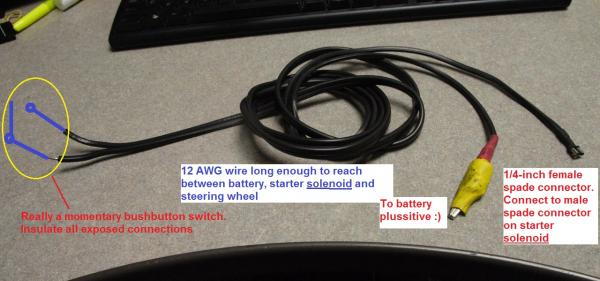
rad4runner-albums-starting+circuit-picture29688-special-service-tool.jpg~original

This setup will help you troubleshoot and/or get you started If something keeps power from getting to your starter solenoid coil. I used it to verify what my suspected problem was.

For troubleshooting:
To check solenoid and downstream to starter motor, clutch gear and flywheel,
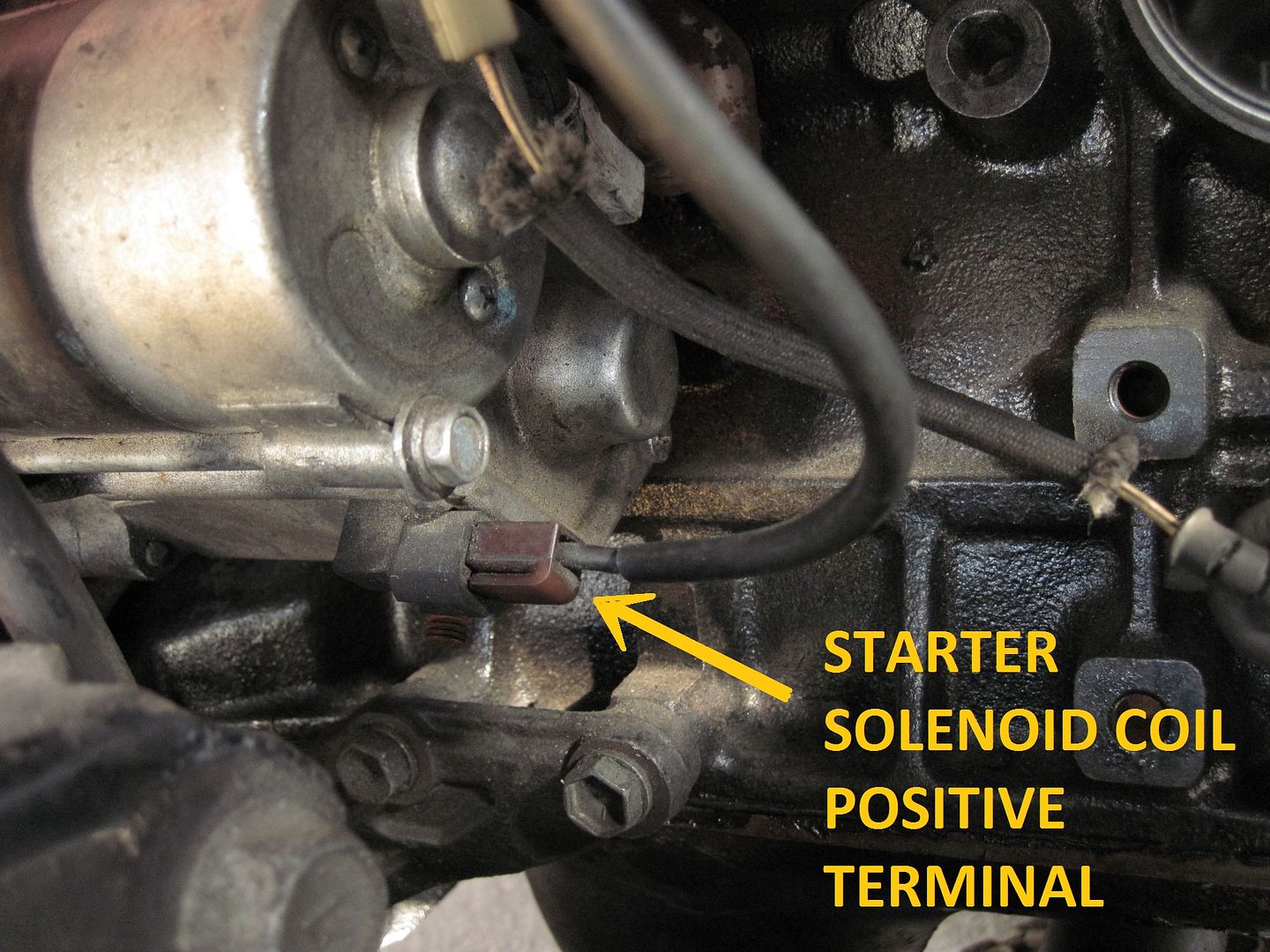
Disconnect this female spade connector from starter solenoid. (This connector supplies power from starter relay to the starter solenoid)
20141018_0003_Solenoid_Coil_Positive_zpsb5ffa0a9.jpg~original


Connect quarter-inch female spade of special tool to male spade on solenoid (where you just disconnected wire from).
Connect Alligator clip to battery plussitive :)
Run end of setup with push-button to driver side.

Ensure safety - neutral, tie not dangling near fans nor belts, etc :)
Push button on. Solenoid should clunk, solenoid contacts will close sending cranking current from superthick wire (connected to battery and screwed-on to terminal on solenoid) to starter motor. Motor should turn, solenoid plunger will actuate clutch, engage starter gears with flywheel gears. You should already know how starter alone or starter engaged with flywheel sounds when turning. See what does not do what it's supposed to do, and go from there.

If all from solenoid and downstream works, troubleshoot from that female spade terminal, upstream to your ignition switch.

To start when you know solenoid and downstream is good, but power is not going to your solenoid coil (i.e., clutch switch defective, starter solenoid defective), or not enough power is getting to your solenoid coil (i.e., wiring flaw explained on my thread), and you have no assistant to jump battery directly to solenoid, do same while attempting to start- at the wheel of course.

Heck!
If you really have to start the engine by yourself while you're looking into the engine compartment, use in combination with the other Special Service Tool - LOL!
 
Last edited:
nice writeups on the mods.
I need to do the switch relocate to the dash, also need to move my ECU to behind the glove box.
 
Rear Window Control From INSIDE Rear Deck

This mod will allow one to roll rear window down from inside the rear deck (i.e., when camping in truck), without having to scramble over to front, put key in ignition in order to lower window from console switch.

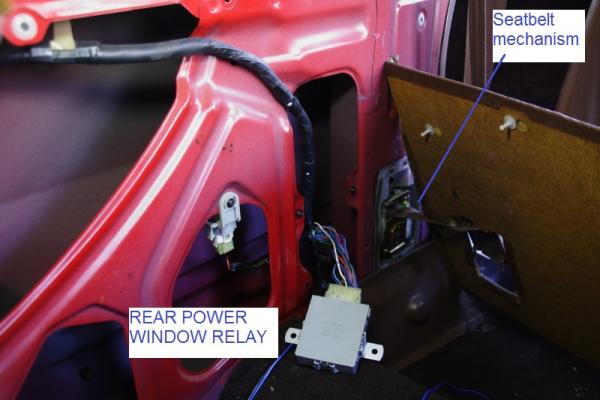
Rear Window/Wiper Relay is behind panel near driver side seatbealt mechanism here:
rad4runner-albums-rear+window+control+mod-picture26042-rear-power-window-relay.jpg~original


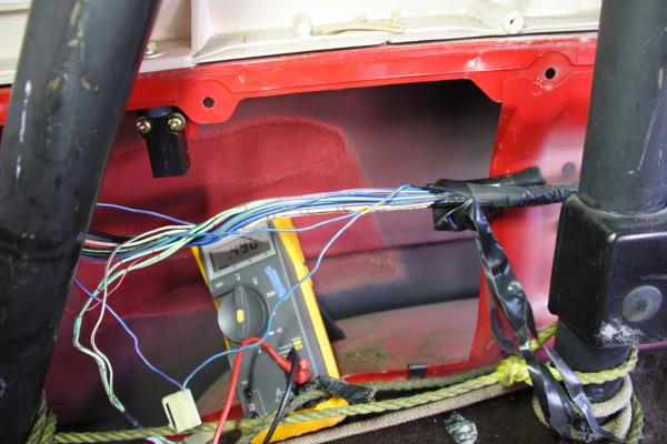
Relevant wiring runs behind panel near left side of rollbar here:
rad4runner-albums-rear+window+control+mod-picture25617-20120819-013.jpg~original

Top Off Switch is also there.

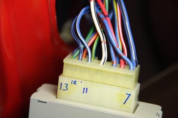
Connector for Rear Window & Wiper Relay here:
rad4runner-albums-rear+window+control+mod-picture25616-20120819-009.jpg~original


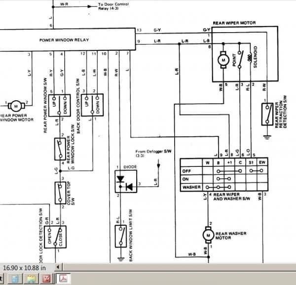
Check against schematic here:

rad4runner-albums-rear+window+control+mod-picture25614-rear-window-control-system.jpg~original


Pin Numbering here:
rad4runner-albums-rear+window+control+mod-picture25615-electrical-piins.jpg~original


This mod will duplicate exactly what the key switch does:
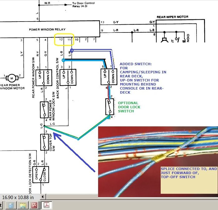
Mod Schematic is here:
Rear_Window_Control_From_Rear_Seatsa_zps9a0957c2.jpg~original


Wire to pin 11 (light blue-white stripe) when connected to ground (via terminal 3 of top-off switch) will lower window.
Wire to pin 12 (lt blue-blk stripe) when connected to ground (via terminal 3 of top-off switch) will raise window.
(To test relay function, touching directly to chassis ground will work regardless of state of top off switch)

Wire a momentary SPDT with center-off switch (Up/Down) exactly same and in parallel with backdoor control switch (key switch),
I recommend to:
  • Locate switches so they are shielded from cargo by roll-bar, and
  • Add fail-safe feature by inserting SPST window lock switch between center terminal of Up/Down switch and terminal 3 of top off switch. (i.e., cargo un-intentionally presses against any of the switches.)
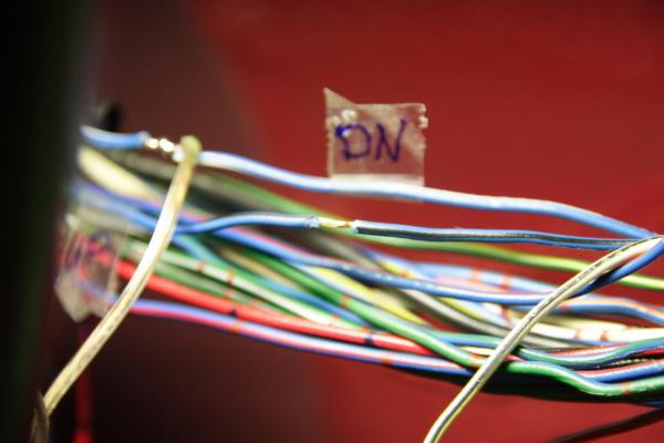
You can do this by carefully stripping off insulation on wires above, and tapping into them. As you can see in pic below, I have labeled Light blue wire with white stripe "DN". Near label, Lt Blue Wire with Black stripe had been stripped to accept tap for "UP" wire.
rad4runner-albums-rear+window+control+mod-picture25621-20120819-019.jpg~original


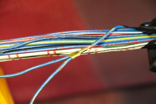
Good place to connect center terminal of SPDT (Up/Down) switch is on this crimp, just forward of top off switch:
rad4runner-albums-rear+window+control+mod-picture25619-20120819-014.jpg~original


Console switch Operation:
In same manner, touching wire going to pin 4 (Green with yel stripe) will lower window, and Pin5 to ground (Red yellow stripe) will raise it. This is where console switch connects. Connecting directly to ground bypasses console rear window lock and rear door lock detection switches.

Here it is in use:
<iframe width="560" height="315" src="https://www.youtube.com/embed/9lDYf00A2E0" frameborder="0" allow="accelerometer; autoplay; encrypted-media; gyroscope; picture-in-picture" allowfullscreen></iframe>
 
Last edited:
Cube On Alternator-To-Battery Wire

Hi guys,
Earlier, I asked what that cube that looks like ferrite choke is around alternator-to-battery wire. Tunrs out to be just another junction point. I updated alternator upgrade post where it was mentioned.
 
No More Brittle Grille Mounting Clips

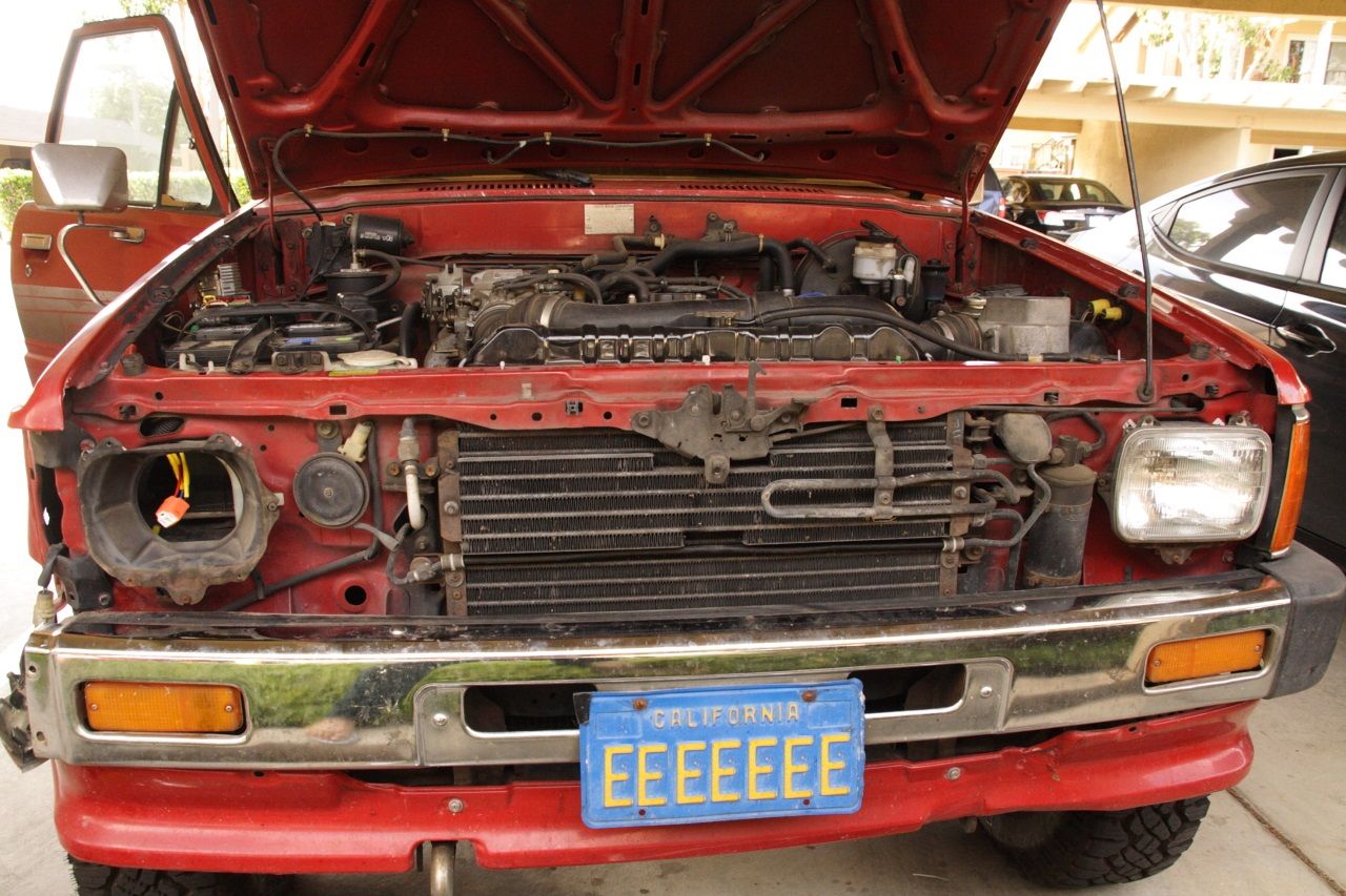
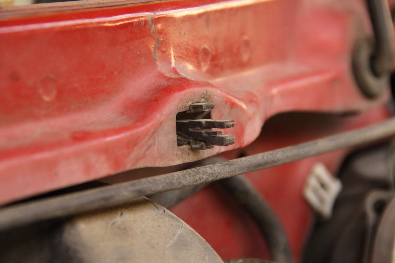
I detest hidden/snap-in mounting hardware. Since I was replacing my sealed beams with the AutoPal housings, I also modified my grill mounting.

007_zps9a926ccc.jpg~original


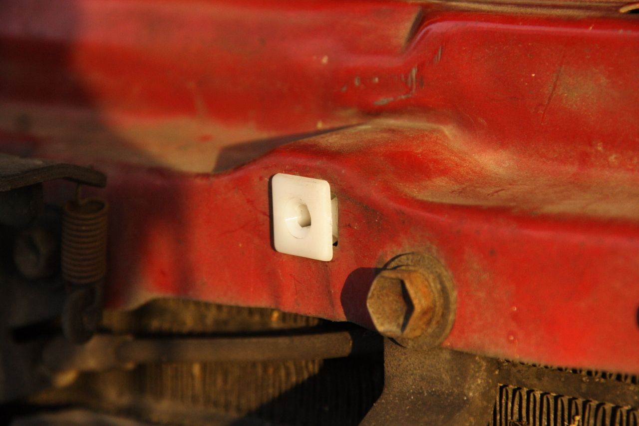
I replaced the snap in clips with expansion nuts from Autozone.

From this:
011_zpsdb2bfc3b.jpg~original


... to this:
013_zps0735dfa9.jpg~original


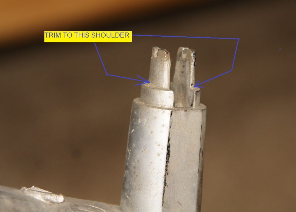
Trimmed posts down to first shoulder.
Untitled_zps322b692f.jpg~original


To something like this (pic of a different post)
026_zps03d51dc5.jpg~original


Opened up slot to accommodate #12 sheet metal screws
025_zpsb6002f9f.jpg~original


I also cut the tip off so the sheet metal screws were down to around 0.75 inch. This way they will not stick out beyond the back of the expansion nut and hit parts behind it.

Now I would not have to grope for release tabs and/or break brittle clips to remove grille; just use common philips screwdriver.
 
Poor Management of Back-up Switch Wiring

Who TF is the genius who combined non-critical back-up light with critical circuits like ECT and Alternator ?!!
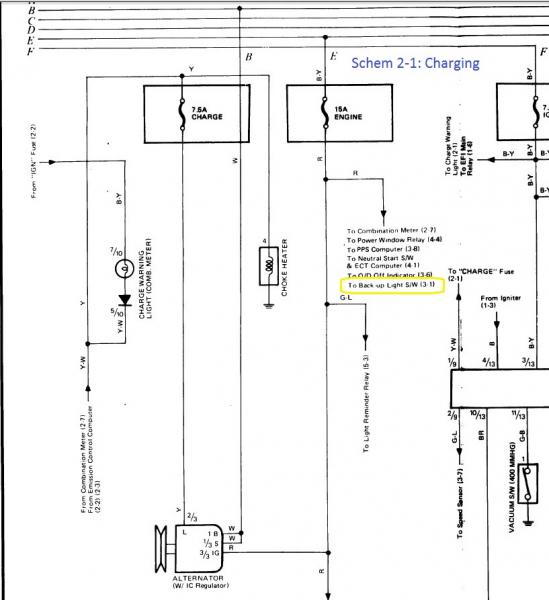
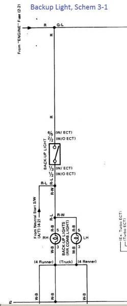
Engine fuse sends power to backup light circuit (yellow rectangle below), and more critical circuits like ECT and Alternator
86-88 4Runner schematic page 2 column 1:
rad4runner-albums-backup+light+circuit+-+system-picture26941-schem-2-1-charging-enginefuse.jpg


86-88 4Runner schematic page 3 column 1:
rad4runner-albums-backup+light+circuit+-+system-picture26942-schem-3-1-backupswitchcircuit.jpg


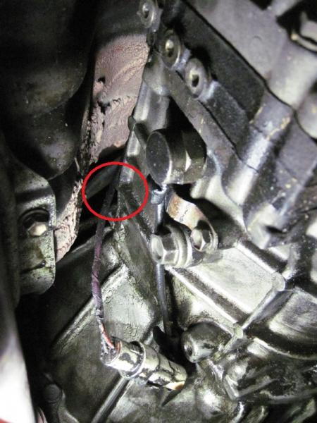
This wire, carrying +12V, rubs against transmission body (Encircled in red below), from vibration, especially from unsecured connector that is heavier than the wire.
rad4runner-albums-backup+light+circuit+-+system-picture26940-img-2566-small.jpg


On Youtube here

Eventually insulation could wear out, short to ground, and blow Engine Fuse (15A). Engine fuse supplies critical parts like the ECT and the excitation field for alternator

Final Solution:
  • Shielded wire with a flexible plastic conduit from the connector, to junction with 4WD switch wire, to past the starter, where there was little chance of rubbing against metal parts.
  • Also did same to 4WD switch wires.
  • Secured connector to transmission body.

This is a good example of why switched ground, where possible, is better than switched positive. Here, when wire shorts to ground, it blows a critical fuse. If the circuit were switched ground (i.e., where this wire provides ground to a relay) and this wire shorts to ground, reverse light will merely come on. No harm done - Heck, I see a lot of Jaguars, Audis and Mercedes on the freeway like that :)
 
Last edited:
Suspension: Removed and Replaced Front Shocks

I had been hearing metallic-sounding creaks around the front suspension when rolling over the tiniest dip and bumps at idle in 2nd gear.
My idler arm had obvious play so I replaced that. Creaking remained.
Finally I had a friend push bumper down and release repeatedly as I felt/listened to the vibration. I localized it to the front shocks. No sound or vibration from control arms as I earlier suspected, too.

Problems Uncovered:
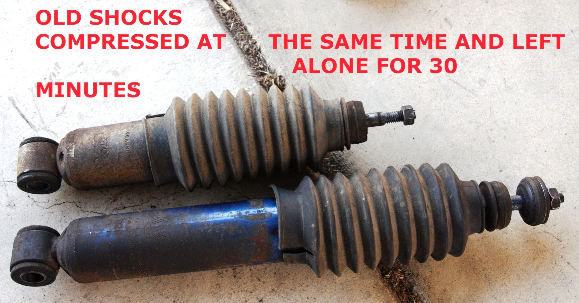
  1. One of the old shocks is totally shut. I compressed them both and left them aside. After about 30 minutes, they looked like below.
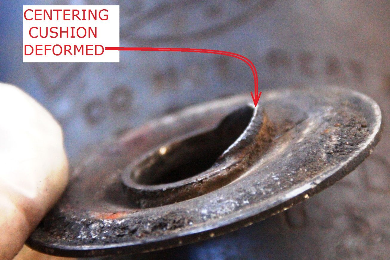
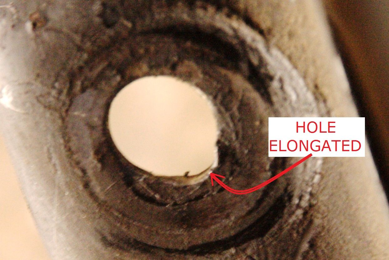
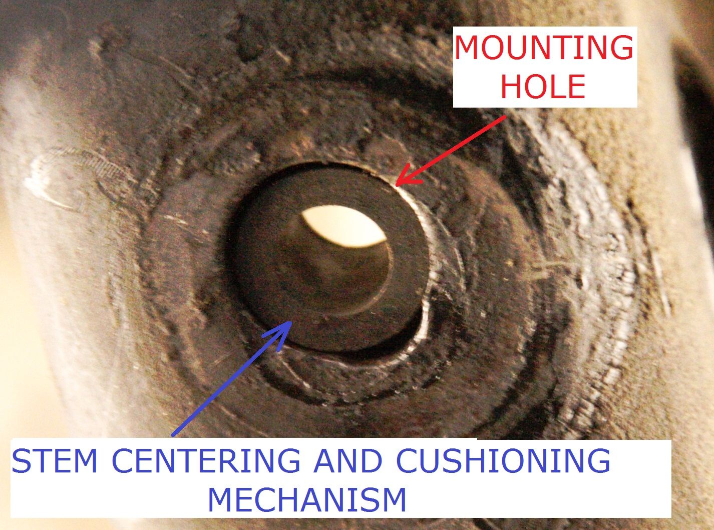
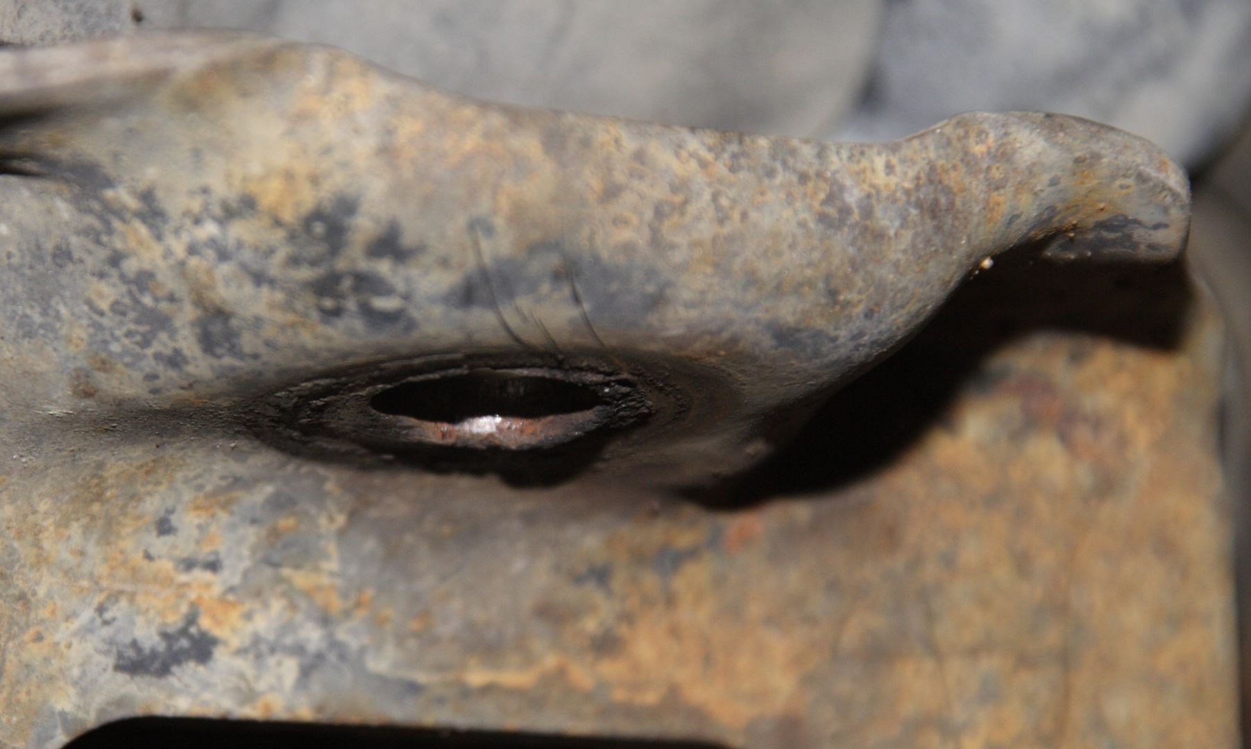
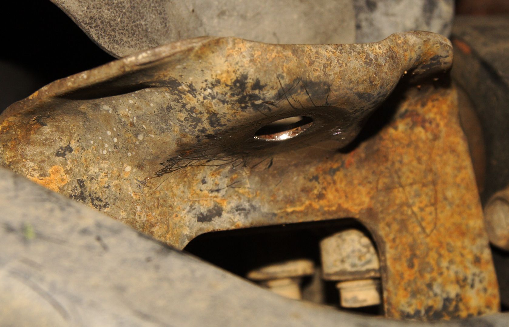
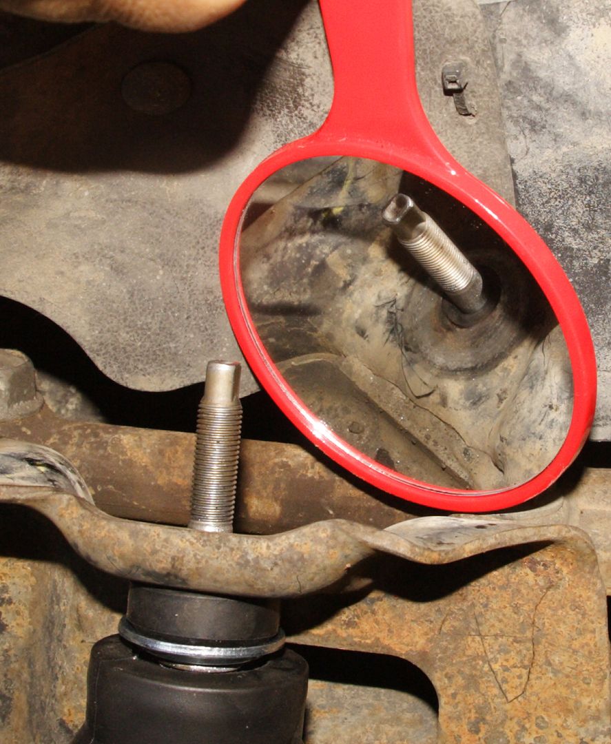
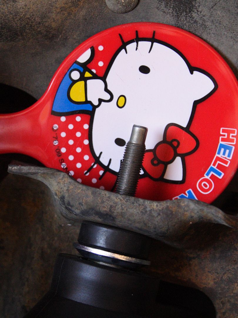
  2. Old shocks do not have effective mechanism to center the stem within the mounting hole. In only has a "sacrificial" centering washer which designer probably hoped would keep bushings centered around the hole and in turn keep the stem from contacting opening. Obviously, that failed. See pictures of deformed mounting hole and shock stem where the two made contact and also caused the creaking sound I had been hearing.
Old Shocks Shut.
DPP_0018_zpsfa9ab3ca.jpg~original


"Sacrificial" Centering Washer Also Deformed:
DPP_0008_zpsfc9843fe.jpg~original


Mounting Hole Deformed:
DPP_0004_zpsf499fb3b.jpg~original

Selecting Replacement Shocks:
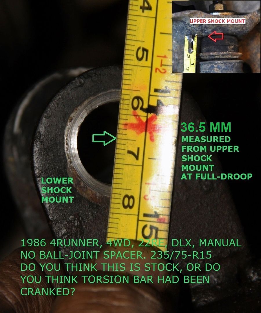
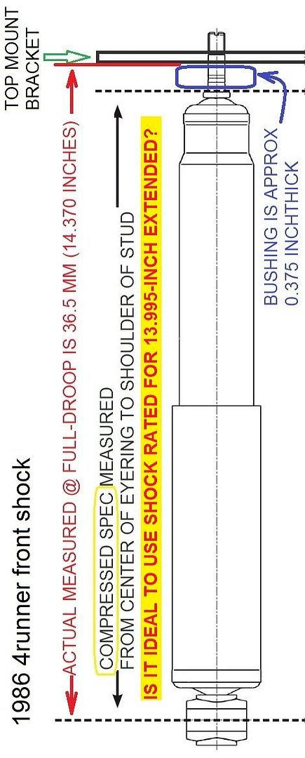
I do not know whether or not torsion bad had been cranked, so I measured actual full droop with shocks removed. I measured 14.370 from center of lower shock mounting bolt to bottom of upper shock mount.

Taking into account the approx. 0.375 inch combined thickness of upper bushing/cushion and one washer, I determined I need shock that had extended length spec of approx 13.995 inches or close.

0020_Full_Droop_zps573dfcb2.jpg~original

Shock_Front_First_Gen_4Runner_zpsc941da2b.jpg~original


I could not measure actual compressed length because that would depend on weight of load, so I just looked for the shocks that satisfied above and with longest travel.

Looking both at OReilly and Autozone selector tool, I narrowed choices down to the KYB GR2/Excel-G (Compressed 9.09", Extended 13.7 in.") and Gabriel Max Control 77479 (Compressed 9.04", Extended 14.14").

I decided on Gabriel Max Control because:
  1. It is longest when extended and shorter when compressed
  2. It has a positive centering mechanism; a "collared" bushing that actually puts rubber between the stem and the metal around the mounting hole.

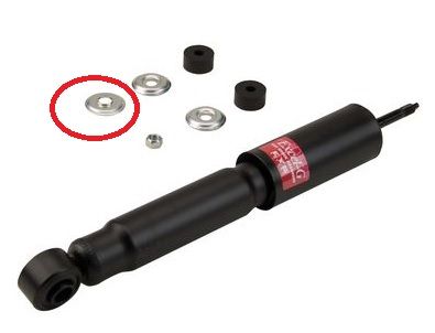
KYB does not have "collared" bushing. It has centering/sacrificial washer that had been proven in-effective.
Untitled_zps93cb733f.jpg~original


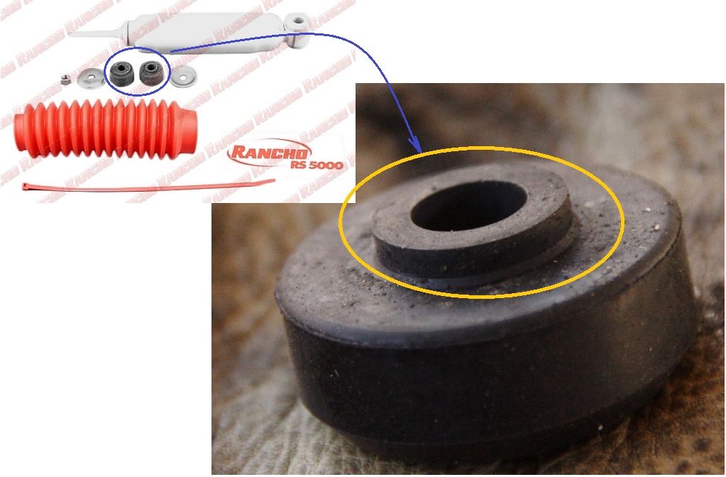
Gabriels, like Rancho's have "collared" bushing.
Gabriel_Bushing_zps90a3a600.jpg~original


Collar on the bushing goes between shock stem and mounting hole, providing positive centering and cushioning.
DPP_0005_zpsfc049b80.jpg~original


Installation:
Plain and simple as described in FSM.
A couple of precautions not mentioned in FSM:
  1. Ensure mounting frame clean and is free of deformity
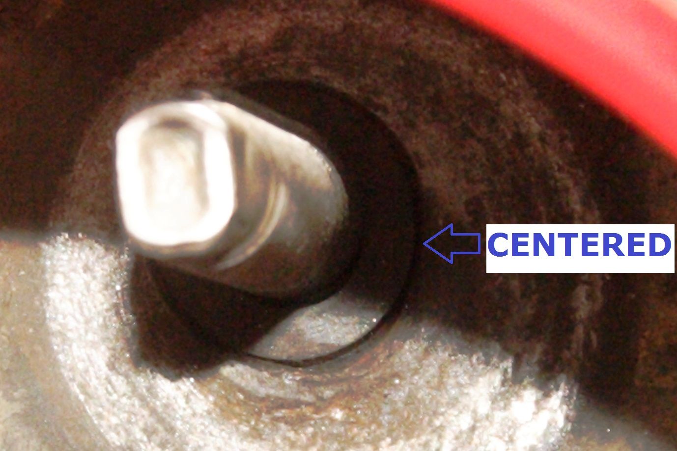
  2. Ensure that bushing collar is actually centered inside the mounting hole and that stem is centered within the collar before installing upper cushion, washer and nut.

Mounting has deformed from metal-to-metal contact:
DPP_0012_zpsf3804c0c.jpg~original


Deformity cleaned/flattened:
DPP_0013_zps3348e38e.jpg~original


Collar Centered In Hole:
DPP_0015_zps294425f2.jpg~original


DPP_0014_zpsa5f6480e.jpg~original


Damn Right, I'm not insecure - LOL!
DPP_0017_zps35547ba6.jpg~original
 
Update25Nov2013

No creaks during my commute on pavement. Will try it on dirt; maybe Anza-Borrego this weekend. Speaking of Anza-Borrego Desert...
Here's the Runner, at home both in Hollywood and the desert - LOL!
474687_10151431526882194_956176260_o.jpg


Here she was with her long lost sister, another Red 86 4Runner:
472341_10151431522057194_1071898666_o.jpg


And at our camp:
921713_10151431522082194_1492931625_o.jpg

My buddy exploring the top of the mud ridge above.

Happy Thanksgiving
 
How the 22R-E Charging System Works - Updated with Google Photos

UPDATED WITH GOOGLE PHOTOS
(I'm posting this here so it will be easier to refer to, rather than re-typing explanation into various threads that need the explanation.)

Here's the 22RE-liable schematic:
EPwyBSwQI83Xpmb4nvPqf0t0Ht8mvxAFA_ans3T8sz1ii9SgDMOIYtEgdkpsQfYzBtIuufHoc7BEbx-1dejXFWVyUS14lm2W7cfN_ANhGBMe3uP8uAUPGskFZ6F7owDhdsvsDDD3zhA8MIbgZ-faUmbUZ9OQmOYdRoLXPxBLLtfhh9qx7bcu7-qlIHcDc213MVgn_d09PXdQVDhjCiLuEBjfeQc1Oggk6IMhAD2-b2DnaffQeRTwkiiOml7Q6OfeLMLI9Icz8Oy4dFL1TFGVAV1OzzPNjzumdkYmR_0kmSNlXTzEnrT_ceMDTQDIAtOllwRhmtELUJlTwBsQ72Cz3dPXJQ1lFyHuWIL8v8E5RklmJkKA0nFMtUiYIhHWdRPguirhVo9MIzgIf4SQpsKypBen2weO23k53y1RqND5WusLts_cTtf1zYuKGDyTXCTuhITvbLt4Sx0iD3f782pAZwhq7qm_-yCOlorsy5Ka_Scjb9N8WdrQrVAeVl62uAJLWidHKjognpKlfSHzlT-YJwM4trVyOaN4Yv1xdmI7HeaWjgZinE_0I1pFGtmICUJ743DR27I_GMK7rKpmbyGCKjoYrRYKPufRkCcQUlf7E1_OnqkrJhBb=w627-h732-no


Close-up of alternator pin-outs is here:
Gd5yPjKkysl0Wv9fqv3OGHfWhjJ7CjTDOFUy0QGvG0BjfcVgz97V1VgUEBWWXHsSgtWFqQsuvUK_K_1Gspukq9Tp4-go-KKijXwwuROXchzrMyT8PGmOPaFsmQq3vSzfFGsLlOBpKpCPZl_Daqkl6rmZb5QL6lnA3OyxOkaoy4VvzNyHQAonEHyhIvyNWqaKMIH10bQW6BylhQ5mV-_LS1GbYyZcrTqua4HBGNaKWmAoJTebLYtSf7PqZZTiO7EvUogiDSGssEXZRY6aD5HUKGh1xBDbNE9auqOGbb8aVPxgc6nPDFli5WO9AUHUJ3WpUiBHkAMsQJS2kJRinhzkPNhdTxbrD0qNZjUaCkvpcf1qYWCigDfrGmtekSGpxO_z76KopZeDv0Ax-zsH0pi-FNVTD1vDPgylC8353C_huZMGHbNVmM9mgyYg1kcUdkyY8G4h06C6rKemASPhnnD3uLUV7AyFxC8umk2iHkaeFylrqCeIpg_W_kJ0ydqW6hlxw50NU4Rz_5tJD9zvry7zyrz2pvulb8aU_p6dD6cwN5v16MaS23wP4Fze38jXj4yFc_oWl_SDHqm_Qu7NDX0HPQo6q5b8sIKMWGChqP4lFIDkQ0PJ74Rz=w801-h601-no


White "B" wire (heavy gauge) to the 80amp fuse
This is the battery charging wire.
From FSM:
With engine from idle to 2000RPM, Voltages at B should be:
13.9 to 15.1 V @25°C (77°F)
13.5 - 14.3V @115°C (239°F)
Temp is probably engine compartment temp.

White "S" to the 40amp (always-on) fuse
This senses actual battery voltage and should be connected as close as possible to battery positive. However, the way it is wired as-built (merely spliced with the B wire downstream of the Fusible link) it will read exactly alternator output and not battery output it is supposed to sense. Anyway, it will only be a small fraction of a volt off; no big deal.

Red "IG" to the Engine fuse
This provides field current to "seed" the charging. This should have steady 12V when ignition is on (coming from Engine fuse). If no 12V here or if this voltage is erratic or engine fuse blows, trace wiring back to Engine Fuse, to "E" battery positive wire from fuse block, and verify that your backup switch or wiring is not shorting to transmission body as shown here.

Yellow "L" to the Charge Warning Light
This should be +12V when alternator is working properly (B voltage 13.5V-15.1V). If B voltage goes lower or higher that that range "L" will go low, and provide ground to negative side of the Charge Light causing it to come on.
(Unfortunately, it also provides ground to Brake Light and A/T Oil temp light- making it confusing to many.)


Most accessible place to measure "L" voltage is here:
3-CdocDN1H0iyuOgwF84A1qZdmFd1knuyiRI3A4coY2kwf5NXLBukxMrtSzgVX1VwZNMk-DLA8Xamb_NvTtWRGkMgdwDt3P9dBRWDobvBeBnx9C5-ENsoDbMqLS3EI8z5hgQZDtmXMLRt-sHERPgJugCD3O8Vw5h2aqFZ2y3Vw-PrQY571RVZDc_0m8_pFhGoAzOkvf8kQzpsxKPzuAUDoxW9S9MpeUb17MjWU4HV-e3WAHZgIqBPViz62D_nTg-Bb2-nKkYh0QWRVzK8Rbk_9WLVNj450Sc5rXSIj3LQRToqqWzblxmn0JWPJQ-5QSKZKGVcoqG88FjTJ1qJM0ziJ0dcqDUau75o9FxlN9tzgLNpe3NwomY89cTHAgRZvHYe3wSNiepApY0GlTbu-HIz736LrWEWx0FgMy7hrJCbPwHovZXfzFjwZ7slpHdDmQ-j3jAxc6p8yw1qgwC-2rC8r3Upu6-hCbmejjNICbJZvoLdcZ4dn94Ez_r08NiGG-nHObqpk7bKlKl_yfB2wBS91-e2gOJbdCHYcqnxXcrMJ0Oz-Y75bhH_t_kvYWaFOY3TwmVqzY_CnJTAxIjVD4sv_zRYu_bZacJC_TU6mNhve_s_vmBFo2b=w800-h600-no


ALTERNATOR HARNESS AND MORE VOLTAGE TESTS OF NORMALLY-FUNCTIONING CHARGING SYSTEM:
The engine compartment wiring harness has an "intermediate" connector along the left inner fender, near the power steering pump, shown below:
OPaKpsgKXZ1ewUvoCBmFwGeP8eXWIUDSLeIqqp6GT1T3Ull8olw17fn4T4aAlMzUBL6NDVjpYB89ZDOgUOg0rwj5ACoxQ1D0eiq6tHgQRK3l1EbuHh6_MJcsNdePN5n9z8snffqsTsoNARsMasfaYRBmi80P2UShx75ivq33H4eEQc2wdUbRz-9yuiYqSc_U56j_AmjSNyNxCS9PUYQKb7c1v-76gB-W2V_kccY5DNYW_Wy7g8bHbyQa06sPHv63aZD_8yM-vHhHmWAYEtidEtBMlYt5tTdWIrkzhyp59npxqGfA1r9zZ-vRw1VtfMiPftG64fWP0uYAQ7STdyx1gvK0XF03P-UUEIoBtWzU4GvcY98qZ6AvpK6sxa_J9C9oagoiMPCkxrRbpmOZmBPl8z0Q33nhZYR6H0_dEy1phZZ1oql84W0cGXAiDnT7QceRIrhQkkfI1sSheqO6glOO-EflwIBIhQqhKtybYYP335GVoEG5DEHYk1UvVjX6lis9QGeKhE1C28SsRVtYsodMgFPhiMCKttgvQaPfL2fgR4xL9QUbn-sem_l7w2xvRpuBmj8taHMjVOyqCMn4A1QHsj6gXUNM4uptQO2W17NBubE=w1380-h776-no
Pin-outs are as follows:
0ehgyp91Cu73NbaYkmaBnilPRG5bLi2QZc6L0A0qmoAvQwtCMSAM09BZqTuqakzWyLe3uiP8srv9bz7nN5oln0BhzYwcKOSaBdOKYwt2YNe-1Qo9FEMDDSvcsBPwRfHTkJ-zi8i3BTeAyzYh-N1W6pCB7v0OQTuEaqm73cdf5m8Orc46mK7A6sXIQW2y6Kf4_vAlhYFAG1KWD0VOsGXrSNHYgCdm1ppW6fY_2oO6Z0a81M9fci_UaRcJCmD9Q2xf9_mVlBDkkUDLOxorUswyVVSjEbwlXR5NFBw1lrhXit1tUwxqaTlXeFS_rZmFlJYQWT50sHLGeyhjV_v-e345CeZJhXSM_S7jfJ-Gj_vtaS3BVhVaaAp7NnfcGOzys7GPj_w1Ni6HwmfK1bBGmTuThZmU5KWvmgbgZsX612IBAgyx_YG64SnKHoiOhuE6w_EL3dGv_2oZA6zmqinKtglNKCYW-nwXFL4P5q27eoL1ldrIUpz9-bcz9AOYiK9DVZ5iHOBW7w5zSg4QzRwHkUE67Oadjer3FnYxAIMWVXFiuDRblRheQNvIVcmZ-HJOLi10ca2fNQlQlziaJUNEch_38u00Soysb7ha4yqQBfNUN64=w856-h776-no

rhYxMDx3iVrlKG9v2l9MPWSqfm4eSzCEPBUXlMs3HE4ESXkczVwsTVQkUZB96leYxSzvbsYrTdDRfFDt8rPfOeKRuhdjIi7LjEjKHgapEQk19BzvxwlvVP4YzpVqoHq6Hr-j6PMdx_7vtTtuQnOEME8DPZ8lpdmTRTXrB8gJbauk0WeQwOHPTVlf_XZ2tc5HTMYgb429nlR4CBBqO_AlxQ579ssiSAYHkVDC2gTO4M8rQJe3eftsBlQr8St0-uv0PjEO1x6DJK8VUP1oHfxTdGk2rzK9fcB24ifE-3zhLBKP6cOARzjF1mWd5NlzJcJYVb3gEIe3a66UoWw_6HRhsyN58-Zzb5tI1goa836U3I_TmW2WXlLx9LdF-p0lEoeHbFv6YAlp-2ysSmiGUIaW_Bly_qPWuFyTvxp8n3maQ2H61jncsn59eTlR809VM1ibgKSd1WscaVaGEntBF-QE6GVfObL8TYBs3VzJ290jGVq6xaCdNPbIUiSAGcfLw29Hqq2nX5aOOPztIuxxxyq-Sw6VdddaxsaooExy_cJ6bTvr6-o-qczXH0nwIpHNuhGvv0VvuzRxDSmC71F-5QmKG54w4cb04ePvRyONEv9fvAg=s776-no
 
Last edited:
Thanks for the grille mount tip. I pulled my grill today to replace a bulb that got on the wrong side of a rock and the headlight surround was cracked so I yanked the whole grill but it was like most of the rest of the truck , a hodge podge of clips, broken clips, and rusted/stripped screws. I will try this mod when I am done improving the grille some. I take it fro your use of MMs and diagrams your an engineer. Just a hunch but after reading your first two posts I thought I was looking at a note from one of my co-workers:)
 

Members online

Forum statistics

Threads
278,309
Messages
3,554,074
Members
248,016
Latest member
Advally Service

Trending content

Back
Top