what an unbelievable difference! - kappa 3.5 dash speakers

What high pass filter did you end using specifically? (so I can copy you :eyebrows:)

I have these installed which gives me a crossover frequency of 400Hz on my Kicker KSC3504: https://www.ebay.com/itm/191726642522

That being said, I think that's really too low for 3.5" speakers and I'm going to swap in some 47uF capacitors for a crossover point around 850Hz (these are about $1.50 each).

Depending on your speaker impedance, check your frequency here: https://www.v-cap.com/speaker-crossover-calculator.php
 
I found another option for wiring, without hacking the original wiring or speaker, or waiting on a harness.. and it was extremely inexpensive.

I was shopping around trying to find the flat pins used in the harness and instead found that a spade terminal fit in there perfectly. The ones that I used had the prongs spaced to where one spade will plug into two spots. So I attached one to the positive and one to the negative side of a speaker cable. Then inserted one of the spades into the factory harness for pins 1 & 2, and the other spade went into the harness for pins 3 & 4. So basically each spade terminal is making the bridge connection to the door speaker, and the wire coming out of that spade terminal goes to the new dash speaker.

Some brands may be shaped slightly different than others. The ones I used were Gardner Bender brand (home Depot), 16-14 gauge, 4-6 stud.

Now that's a pretty novel approach that I didn't think about! You'd probably want to tape it to make sure it doesn't come loose, but seems like it would work well.
 
I have these installed which gives me a crossover frequency of 400Hz on my Kicker KSC3504: https://www.ebay.com/itm/191726642522

That being said, I think that's really too low for 3.5" speakers and I'm going to swap in some 47uF capacitors for a crossover point around 850Hz (these are about $1.50 each).

Depending on your speaker impedance, check your frequency here: https://www.v-cap.com/speaker-crossover-calculator.php

Thanks for the links. Took me a little self education to understand it all.

For anyone else that got the JBL GX302's, the impedance is 2.3 ohms. To get a crossover point at around 800-850Hz (which is about target from what I can gather for a 3.5" speaker) you'll need an 80 mfd non polarized cap which you can pick up for about 2 bucks each from parts express.
 
I have these installed which gives me a crossover frequency of 400Hz on my Kicker KSC3504: https://www.ebay.com/itm/191726642522

That being said, I think that's really too low for 3.5" speakers and I'm going to swap in some 47uF capacitors for a crossover point around 850Hz (these are about $1.50 each).

Depending on your speaker impedance, check your frequency here: https://www.v-cap.com/speaker-crossover-calculator.php

Followup question:

Given the existing presence of the capacitor on the new speakers, would running a “bass blocker” effectively create problems for the high pass filter for the tweeter?

In other words, do you end up running two capacitors in series by using a bass blocker?
 
Last edited:
Finally got my front harnesses in from Seicane on Ebay, and it looks like they'll work just fine. Total cost for both was $12 shipped, so quite a bit less than Tacotunes. Only drawback is waiting a week or two for shipping.

Do you have a link by chance? If my search is correct, that seller is no longer registered
 
Followup question:

Given the existing presence of the capacitor on the new speakers, would running a “bass blocker” effectively create problems for the high pass filter for the tweeter?

In other words, do you end up running two capacitors in series by using a bass blocker?

That's actually a very good question, and something I haven't really thought about since bass blockers are so prevalent with coaxial speakers. Although I'm an engineer, I'm the wrong type to answer this question, haha. That being said, here's my take on it, even though I'm sure there are other more complex factors involved in the circuit:

As an example, a 4-ohm coaxial is most likely an 8ohm woofer and 8ohm tweeter wired in parallel, with the tweeter's filter being in series with the tweeter only. A good crossover point for a tweeter is 3000Hz, so it could be using a 6.6uF cap as it's filter, assuming 8ohms impedance. If you were to put a 50uF cap in series with it, that would essentially be equivalent to about 5.83uF (caps in series don't add, and are calculated like resistors in parallel). This would bump the tweeter crossover point up to about 3400Hz, meaning that the tweeter would cover everything from 3400Hz to 20kHz. In my mind this would be a very small change given the broad frequency range that a tweeter covers, and the woofer could still probably handle everything from 3000-3400Hz. Also, the 6db/octave slope that a capacitor gives isn't too steep, which allows more of an overlap between drivers and would help blend the sound.

Take all of the above with a grain of salt, since I'm not an electrical or audio engineer. I attempted to do some googling, but came up empty handed so I'm inclined to ask this question on a forum that specializes in this sort of thing.
 
Researching the forum and decided to order the JBL GX302's for the dash. What is the best / easiest way to mount these? I've seen posts with modifications but also some indicating they were simple to install with no further explanation. Wanting to tackle this on my own, but new to audio upgrades. Appreciate the help.
 
Finally got my front harnesses in from Seicane on Ebay, and it looks like they'll work just fine. Total cost for both was $12 shipped, so quite a bit less than Tacotunes. Only drawback is waiting a week or two for shipping.

For those of you questioning whether or not to remove the factory capacitor, I think it should be done. Mine were 6.8 uF, which equates to a high pass frequency of about 5800hz on a 4ohm speaker. Some of the speakers people have been installing are closer to 2.5ohms, which would make it even worse at over 9000hz.

Also, the capacitors that are found on your new speakers are most likely just a high pass filter for the tweeter only, and do nothing to protect the woofer (there are a few exceptions here, such as the Infinity which has the crossover assembly wired in line with the speaker).

Can you please explain how you wired these 4 wires into your speakers?
 
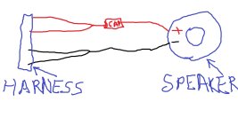
So Im finally getting around to doing this mod. Ive read the entire post a few times, bought the speakers and Bass Blockers and are just about ready to go. Since I am a wiring idiot I wanted to confirm this before I got started, and stuck. The 2 negatives get tied together to form 1 negative and then directly to that dangley thing on the speaker, the 2 positives get tied together to form 1 positive then to the Bass Blocker, then the 1 blue wire from the other side of the Bass Blocker goes to the positive on the dangley thing off the speaker. Is that correct?

Is this how you guys would wire the 4 wire taco tunes adapter? Would the bass blocker being inline of both wires have any impact on the 6x9?
 
Thanks for the links. Took me a little self education to understand it all.

For anyone else that got the JBL GX302's, the impedance is 2.3 ohms. To get a crossover point at around 800-850Hz (which is about target from what I can gather for a 3.5" speaker) you'll need an 80 mfd non polarized cap which you can pick up for about 2 bucks each from parts express.

Found these on Amazon, can't find the cap rating though. Are they in the ballpark?

https://www.amazon.com/dp/B00H3RL6NI/?coliid=I1AMCMU9HAGYEE&colid=3GEZL9J7LD1HP&psc=0&ref_=lv_ov_lig_dp_it


.
 
Can you please explain how you wired these 4 wires into your speakers?

Make sure you follow the factory harness colors I posted above in post 526. They should coordinate properly with the red positive and black negative wires of your aftermarket harness when plugged in. You'll connect both positives together (either solder or one side of butt splice), and then connect your capacitor to that junction before connecting to + on speaker. Then, connect both negatives together and run one wire from that junction to your speaker negative. I've attached an extremely crude MS paint drawing since I don't feel like firing up AutoCAD or Visio, haha.
 

Attachments

  • Speaker.jpg
    Speaker.jpg
    83.8 KB · Views: 1,074
Make sure you follow the factory harness colors I posted above in post 526. They should coordinate properly with the red positive and black negative wires of your aftermarket harness when plugged in. You'll connect both positives together (either solder or one side of butt splice), and then connect your capacitor to that junction before connecting to + on speaker. Then, connect both negatives together and run one wire from that junction to your speaker negative. I've attached an extremely crude MS paint drawing since I don't feel like firing up AutoCAD or Visio, haha.

Thank you, this is what I was envisioning
 

Members online

No members online now.

Forum statistics

Threads
278,316
Messages
3,554,120
Members
248,016
Latest member
Advally Service

Trending content

Back
Top