Wiper/washer switch mist mod

Even Steven said:
I believe there are larger caps that are wider, but not taller. If you look at the pics, you can see that the two caps are the same height (or very close) and the big difference is in width.

The next available value at Radio Shack which is what Kmvreter has available to him so far is 200uf which is double what we have now which is why I started to get worried.
 
Spider5 said:
I found a small 130uF Cap with a voltage rating rather high but should be a problem.

http://www.amazon.com/Solen-130uF-250V-Polypropylene-Capacitor/dp/B0002M71LW

Biggest issue might be that it isn't poparized. If the leads are long enough you might be able to mount it upright though like the existing cap.

Yeah, unfortunately it has to be electrolytic. The biggest problem here is that the only switch we can look at is all the way up in Canada and it makes it really hard to take measurements when you can't tell for sure where to measure. Also it has to keep going back into his daily driver and if we bust anything we leave a guy who probably needs his wipers a lot more often than I do stranded. And that switch is not cheap to replace. Kind of frustrating.
 
Last edited:
drmorbius said:
Yeah, unfortunately it has to be polarized . The biggest problem here is that the only switch we can look at is all the way up in Canada and it makes it really hard to take measurements when you can't tell for sure where to measure. Also it has to keep going back into his daily driver and if we bust anything we leave a guy who probably needs his wipers a lot more often than I do stranded. And that switch is not cheap to replace. Kind of frustrating.

Good point. If others are truly interested in this modification, maybe we can get a few of us to chip in to purchase a new switch and let Kmvreter experiment with his old switch. Rockauto.com sells new replacement switches for around $150 I believe, so it wouldn't be too expensive if there were enough of us to chip in.

Any takers?
 
What about a new approach and bypassing the resistor with a wire, since the resistor has such a small value. Although it might reduce the time it at least tells us more about the circuit without having to add any parts.
 
Last edited:
OK guys, here's where I'm at.

I'm not worried about busting anything. I've had it apart a few times and it's actually relatively "easy" to get back together (ps. I'm not reinstalling the steering wheel trim until this is all finished.) I can always reinstall the existing cap if the experiment blows. I need to work on my de/solder skills but I'll manage. Any tips on soldering? Should I pre-cut the pieces of solder and melt them in place or is it easier to solder by melting from the wire/roll (like plumbing solder)?

The main reason I am steering clear of changing a resistor is because it's not easily accessible on the board under the switch structure, so resistor talk is a moot point.

On to the cap...
I've called around. We used to have an excellent electronics parts counter store but he went broke so I ended up at The Source (Radio Shack up here.) They have an assortment pack with either 220uF 25V or 220uF 50V radial caps. The actual "package" size of the cap is no bigger than the existing so fit isn't an issue. They just aren't 16V. I surfed for info and it looks like I can use the higher Volts without harm. Can someone confirm this? This (and time to install) is my only holdup right now.
 
Kmvreter said:
OK guys, here's where I'm at.

I'm not worried about busting anything. I've had it apart a few times and it's actually relatively "easy" to get back together (ps. I'm not reinstalling the steering wheel trim until this is all finished.) I can always reinstall the existing cap if the experiment blows. I need to work on my de/solder skills but I'll manage. Any tips on soldering? Should I pre-cut the pieces of solder and melt them in place or is it easier to solder by melting from the wire/roll (like plumbing solder)?

The main reason I am steering clear of changing a resistor is because it's not easily accessible on the board under the switch structure, so resistor talk is a moot point.

On to the cap...
I've called around. We used to have an excellent electronics parts counter store but he went broke so I ended up at The Source (Radio Shack up here.) They have an assortment pack with either 220uF 25V or 220uF 50V radial caps. The actual "package" size of the cap is no bigger than the existing so fit isn't an issue. They just aren't 16V. I surfed for info and it looks like I can use the higher Volts without harm. Can someone confirm this? This (and time to install) is my only holdup right now.

The high voltage will not do any harm the RC circuit just will not be as accurate in the timing. Meaning the delay might be a couple seconds different from one cycle to the next.
 
Spider5 said:
The high voltage will not do any harm the RC circuit just will not be as accurate in the timing. Meaning the delay might be a couple seconds different from one cycle to the next.

Can you explain that some more? I'm not sure I agree with what you're saying, if I understand you correctly.
 
I found an excellent site for de/soldering advice: http://www.epemag.wimborne.co.uk/solderfaq.htm
I got 2 different desoldering tools: a vacumn bulb type and a pump type. I'll try the (cheap) bulb first, resort to the pump if I have to.

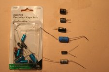
I picked up the assortment pack of caps at The Source (sku # 2720802; C$5.99.) 21 caps in all, of which 6 are options for this application (see pic below.)

In order of preference from top to bottom:

220uF / 25V radial has same leads and is roughly same size as the original on the board (best plug-n-play.)
220 / 25 radial but for some reason is smaller size.
220 / 16 is the right Volts but isn't radial and has short leads that will be tough to fit.
200 / 16 "Big Blue" is my choice (right Volts; dbl uF rating; long leads even though it isn't radial.)

Next 2 are both 100 / 16 so I can replace the original if I royally screw this up. I can also use one of these to test our theory by doubling up on the current cap (there is room to leave the existing cap in place and add one of these.)

So, I'm waiting for words of wisdom and your direction...

 
Pic of caps:
 

Attachments

  • t4rwwsw15.jpg
    t4rwwsw15.jpg
    66.1 KB · Views: 155
Last edited:
Spider5 said:
The high voltage will not do any harm the RC circuit just will not be as accurate in the timing. Meaning the delay might be a couple seconds different from one cycle to the next.

I already found minor differences in the delay timing while measuring it for the stock baseline values. I attribute this to temperature differences because I timed it at startup (Canadian cold) and later with a warm cabin, up to temp.

Baseline (swipe to swipe; average measured over a 10 sweep cycle):

Slow = 8.5 to 8.75 seconds

Fast = 2.60 to 2.98 seconds
 
Kmvreter said:
OK guys, here's where I'm at.

I'm not worried about busting anything. I've had it apart a few times and it's actually relatively "easy" to get back together (ps. I'm not reinstalling the steering wheel trim until this is all finished.) I can always reinstall the existing cap if the experiment blows. I need to work on my de/solder skills but I'll manage. Any tips on soldering? Should I pre-cut the pieces of solder and melt them in place or is it easier to solder by melting from the wire/roll (like plumbing solder)?

The main reason I am steering clear of changing a resistor is because it's not easily accessible on the board under the switch structure, so resistor talk is a moot point.

On to the cap...
I've called around. We used to have an excellent electronics parts counter store but he went broke so I ended up at The Source (Radio Shack up here.) They have an assortment pack with either 220uF 25V or 220uF 50V radial caps. The actual "package" size of the cap is no bigger than the existing so fit isn't an issue. They just aren't 16V. I surfed for info and it looks like I can use the higher Volts without harm. Can someone confirm this? This (and time to install) is my only holdup right now.

The higher voltage rating on the cap just tells you how many volts the cap can take without going "pop". We just don't want to go under 16 volts. Sounds like a go on big blue.
 
Last edited:
drmorbius said:
The higher voltage rating on the cap just tells you how many volts the cap can take without going "pop". We just don't want to go under 16 volts. Sounds like a go on big blue.

Thanks, that's what I thought. I looked closer and the smaller cap is 33uF / 25V so that jives with the theory.

I pulled the switch again and it looks like I can play with temporarily connecting caps in parrallel with the existing by pushing the leads into the base. The problem is that the existing cap doesn't have any pos (+) or neg (-) direction markings. I looked every which way. Which way is the polarity based on the wiring schematic? Is pos (+) toward Pin 16 or the resistor? (The smaller cap has neg (-) markings but that doesn't help.)
 
Kmvreter said:
Thanks, that's what I thought. I looked closer and the smaller cap is 33uF / 25V so that jives with the theory.

I pulled the switch again and it looks like I can play with temporarily connecting caps in parrallel with the existing by pushing the leads into the base. The problem is that the existing cap doesn't have any pos (+) or neg (-) direction markings. I looked every which way. Which way is the polarity based on the wiring schematic? Is pos (+) toward Pin 16 or the resistor? (The smaller cap has neg (-) markings but that doesn't help.)

If it's not marked, it is most likely a non-polarized cap, which can be connected in either direction.
 
Hmmm... most electrolytic caps are polarized. I had to look it up to be sure. Can you trace the circuit on the board to determine the correct polarity? You might be able to use the known polarity of the small cap to help you determine the polarity of the large cap. It's difficult to tell from the pictures.
 
Kmvreter said:
Thanks, that's what I thought. I looked closer and the smaller cap is 33uF / 25V so that jives with the theory.

I pulled the switch again and it looks like I can play with temporarily connecting caps in parrallel with the existing by pushing the leads into the base. The problem is that the existing cap doesn't have any pos (+) or neg (-) direction markings. I looked every which way. Which way is the polarity based on the wiring schematic? Is pos (+) toward Pin 16 or the resistor? (The smaller cap has neg (-) markings but that doesn't help.)

According to the schematic pin 16 eventually goes to ground and thats where I'd put the cap minus. Are you sure there is no marking sometimes the neg side is marked by a white stripe.
 
Last edited:
Even Steven said:
Can you explain that some more? I'm not sure I agree with what you're saying, if I understand you correctly.

The higher rated capacitors are made to handle more voltage before they fail. Therefore the plates are made thinker and the internals are more rebust, however this changes the accuracy of the rating and charge time which are not as constant as the lower voltage rated Cap especially when running a low voltage through them.
 
Kmvreter said:
OK guys, here's where I'm at.

I'm not worried about busting anything. I've had it apart a few times and it's actually relatively "easy" to get back together (ps. I'm not reinstalling the steering wheel trim until this is all finished.) I can always reinstall the existing cap if the experiment blows. I need to work on my de/solder skills but I'll manage. Any tips on soldering? Should I pre-cut the pieces of solder and melt them in place or is it easier to solder by melting from the wire/roll (like plumbing solder)?

The main reason I am steering clear of changing a resistor is because it's not easily accessible on the board under the switch structure, so resistor talk is a moot point.

On to the cap...
I've called around. We used to have an excellent electronics parts counter store but he went broke so I ended up at The Source (Radio Shack up here.) They have an assortment pack with either 220uF 25V or 220uF 50V radial caps. The actual "package" size of the cap is no bigger than the existing so fit isn't an issue. They just aren't 16V. I surfed for info and it looks like I can use the higher Volts without harm. Can someone confirm this? This (and time to install) is my only holdup right now.

As for soldering I usually just tear off 8" enough so you can hold it in your hand and aim it. Also just so we are clear .031 rosin core is a good size. No acid core.
 
Spider5 said:
The higher rated capacitors are made to handle more voltage before they fail. Therefore the plates are made thinker and the internals are more rebust, however this changes the accuracy of the rating and charge time which are not as constant as the lower voltage rated Cap especially when running a low voltage through them.

Well, from what I remember all electrolytic caps are notorious for inconsistency. I believe they are among the lowest cost caps you can buy. I'm not so sure the voltage rating has an effect on their accuracy.
 

Members online

Forum statistics

Threads
278,309
Messages
3,554,071
Members
248,016
Latest member
Advally Service

Trending content

Back
Top