DIY: Interior LED swap (cluster, HVAC, switches, window, *steering wheel)

Simple question, I looked through this thread can’t seem to find anywhere anything on if this swap will allow the new led’s to be dimmed?
Some of the posts look beautiful....and oh so very bright....
Before I do this swap I just want to make sure that you can dim the new led’s in the cluster, night driving for myself is best with a VERY dim dash...
Many thanks in advance.

Yes, they are dimable.
 
[MENTION=59048]S p a r k y[/MENTION] (so you know what is happening to my cluster)

Now my tach goes out as does the left part of the ODO display. The speedo needle appears to dim when this happens. Anyway, I'm trying to get a limited cluster to replace the gas needle (previously mentioned: it was damaged on the first LED attempt and I'm assuming that is why it has always appeared dim to me).

8vpuRbfl.jpg


So:
1) my speedo needle flickers from time to time
2) Tach needle goes out entirely from time to time as well.
3) Left side of ODO goes out when tach does.
4) gas needle has always been a tad dim to me.

I had Yosh2000 resolder the white backlight LEDs b/c they were going out...... No problems since. The needles were never redone and I suspect cheap ass LEDs were used.

Sparky: I haven't forgotten about ya!!!!! Soon as I can score a limited cluster, I'll give ya a holler!
 
6volt question:

I'm trying to do the HVAC Multi Display.
I would prefer not to do the 12v mod.

If I have spare neo4 holders, can I order a different LED bulb to put in the holder? What kind of specs would I need to look for in the LED?
 
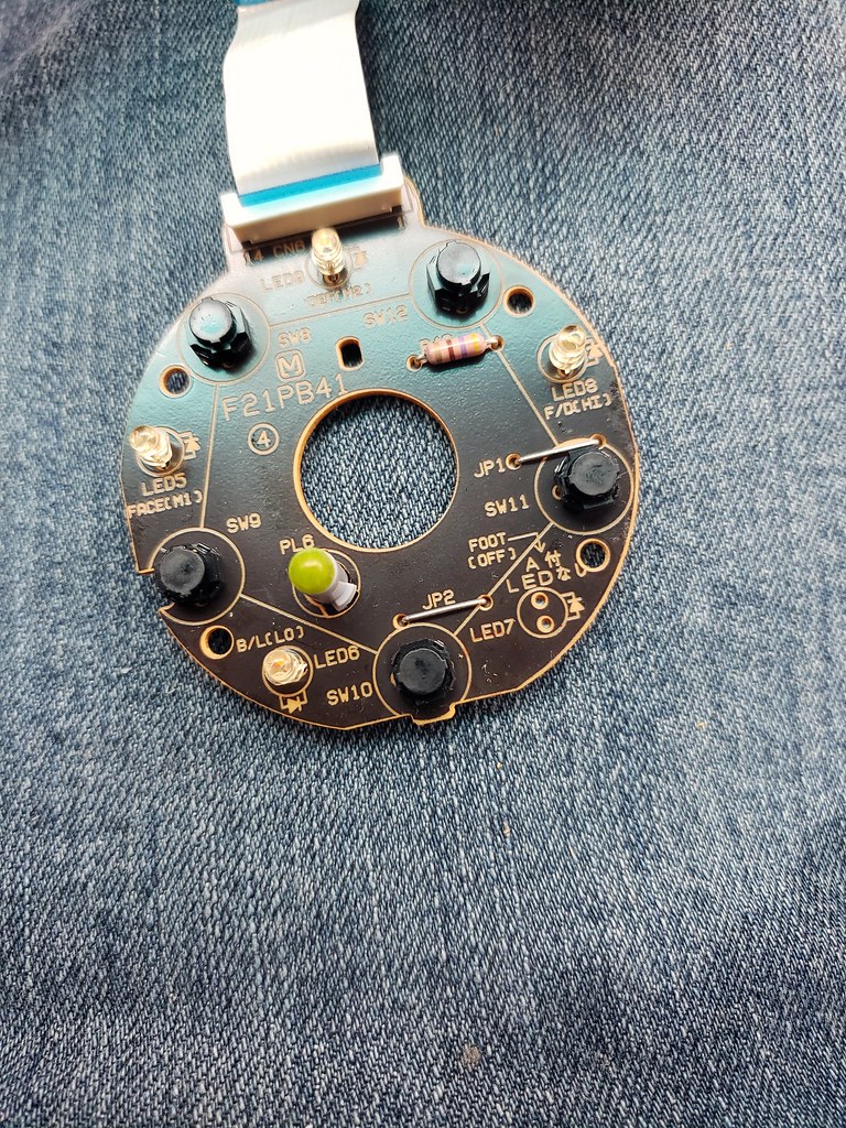
So I replaced lamps over the weekend and everything went great...except for one. It looks like Toyota never installed an LED in position 7 (OFF).

40923100123_99f43ed032_b.jpg


Does anyone know the part number for this lamp so I Can solder it in?
 
So I replaced lamps over the weekend and everything went great...except for one. It looks like Toyota never installed an LED in position 7 (OFF).

40923100123_99f43ed032_b.jpg


Does anyone know the part number for this lamp so I Can solder it in?

One doesn't exist. I had an LED soldered in mine. Not sure of the specs, but solder one in (mine is red) and it should be fine.
 
So I replaced lamps over the weekend and everything went great...except for one. It looks like Toyota never installed an LED in position 7 (OFF).

40923100123_99f43ed032_b.jpg


Does anyone know the part number for this lamp so I Can solder it in?

they take 3mm led, you can do what ever color you want.
 
So I replaced lamps over the weekend and everything went great...except for one. It looks like Toyota never installed an LED in position 7 (OFF).

40923100123_99f43ed032_b.jpg


Does anyone know the part number for this lamp so I Can solder it in?

If you have a meter, check the voltage between those two terminals before you solder in an led. I tried it with my truck a few years ago and it blew the led instantly because it had 12 volts going to it. Some folks claim it worked for them but that was not the case for me.
 
If you have a meter, check the voltage between those two terminals before you solder in an led. I tried it with my truck a few years ago and it blew the led instantly because it had 12 volts going to it. Some folks claim it worked for them but that was not the case for me.

It should have 12 volts going to it. How else will the LED illuminate?
 
If you put 12 volts directly to an led it will blow. They are designed to run on 2 to 4 volts DC depending on color.

Yea, you are right. I didn't realize that.

Cuts for this red one says 1.8-2.2v.

https://www.sparkfun.com/datasheets/Components/LED/COM-00533-YSL-R531R3D-D2.pdf

However, this one from Amazon has a resistor built in, allowing 12v operation: https://www.amazon.com/12-Volt-LEDs-Internal-Resistor/dp/B00RRBWUMG?th=1

My guess is it depends on which LED you put in which will determine why some work and some don't.
 
This is what I did.

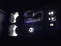
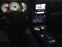
I love all of the mods posted on here, it's really motivated to do my own. Check it out. 1st pic shows the new switches I installed, a switch for the LED light bar and a switch for the rear camera instant on (comes in real handy when try to hook up the trailer). Also installed cup holder led discs as well as 4runner smokers kit with USB chargers with led rings instead of cigarette lighter. I really like how it turned out. Other pics show led swap outs on dash. Pictures don't do it justice.
 

Attachments

  • IMG_1542-1.jpg
    IMG_1542-1.jpg
    61 KB · Views: 781
  • IMG_1525-1.jpg
    IMG_1525-1.jpg
    66.5 KB · Views: 824
  • IMG_1535-1.jpg
    IMG_1535-1.jpg
    31.7 KB · Views: 856
Last edited:
I love all of the mods posted on here, it's really motivated to do my own. Check it out. 1st pic shows the new switches I installed, a switch for the LED light bar and a switch for the rear camera instant on (comes in real handy when try to hook up the trailer). Also installed cup holder led discs as well as 4runner smokers kit with USB chargers with led rings instead of cigarette lighter. I really like how it turned out. Other pics show led swap outs on dash. Pictures don't do it justice.

Where did you get the lights for your Multifunction/Clock display?
I can't find any LEDs in stock that have the right voltage. Tried the 12v mod, didn't like the outcome.
 
So I originally swapped some white LEDs into my center console switches/HVAC, and was very underwhelmed, and had lots of hotspots. Decided to switch to red, this time bought these:

https://www.amazon.com/gp/aw/d/B072XGL9XK?psc=1&ref=ppx_pop_mob_b_asin_title

The issue with all these China neowedge housings is they are crap and don’t lock in place well, so I unbent the LED wires of both the stock bulbs and new LEDs and swapped housings. Much better fit.

Additionally for the HVAC data readout display, the white LEDs I put in had the same issue as everyone else: they were dim and had a brownish hue, even after doing the 12V mod. So I did a tear down of the entire panel and finally got to the LCD display. Tried a lot of light positions both directly behind the LCD and further back and they all sucked for light distribution with the LEDs. What I ended up doing was drilling out the stupid plastic pieces that block the LEDs from directly shining on the LCD. Once those were off I got MUCH better light distribution. There is a slight hot spot in front of each bulb that is minuscule enough for me to be very satisfied.


The photos I took highlight the hotspot and make it look way worse than it is. To the naked eye it’s barely visible. Color looks Amber in photo but is deep red.

full
 
Last edited:
Needle Color

Here is my write up on how to change the color of your interior lights for the 4th Gen 4Runner.

**Disclaimer: This "how to" is for informational purposes only. I take no responsibility for any damage to your vehicle. If you do not have basic soldering skills, please do not attempt. Serious damage could occur.**

Tools needed to remove cluster/steering wheel controls/HVAC unit:
10mm Socket (used to take apart dash/disconnect negative battery)
Small flat head screwdriver (remove steering wheel panels and unscrew bulb holders)
medium Phillips screwdriver (remove steering wheel control)
T-30 Hex Driver (disconnect Air Bag from steering wheel)

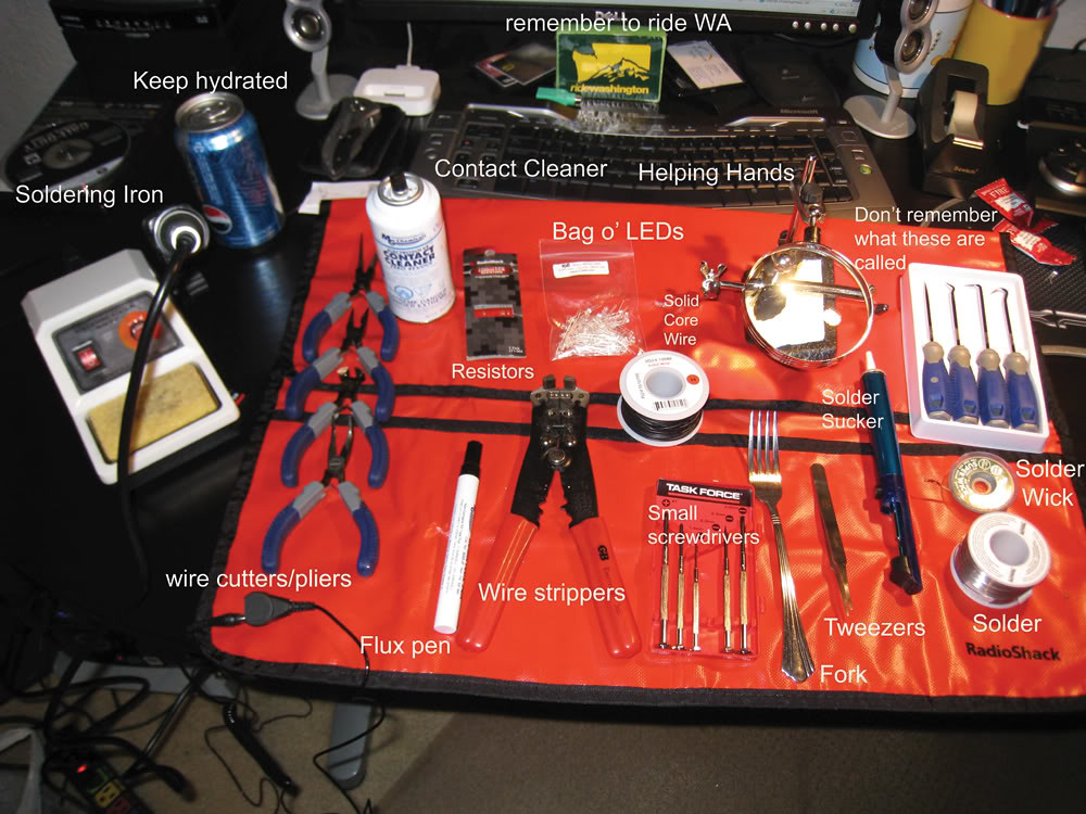
Tools needed or suggested to complete LED swap:
35682255602_b79b08ea63_b.jpg

I know the fork is ghetto but it works...


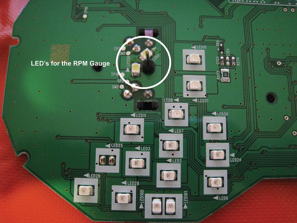
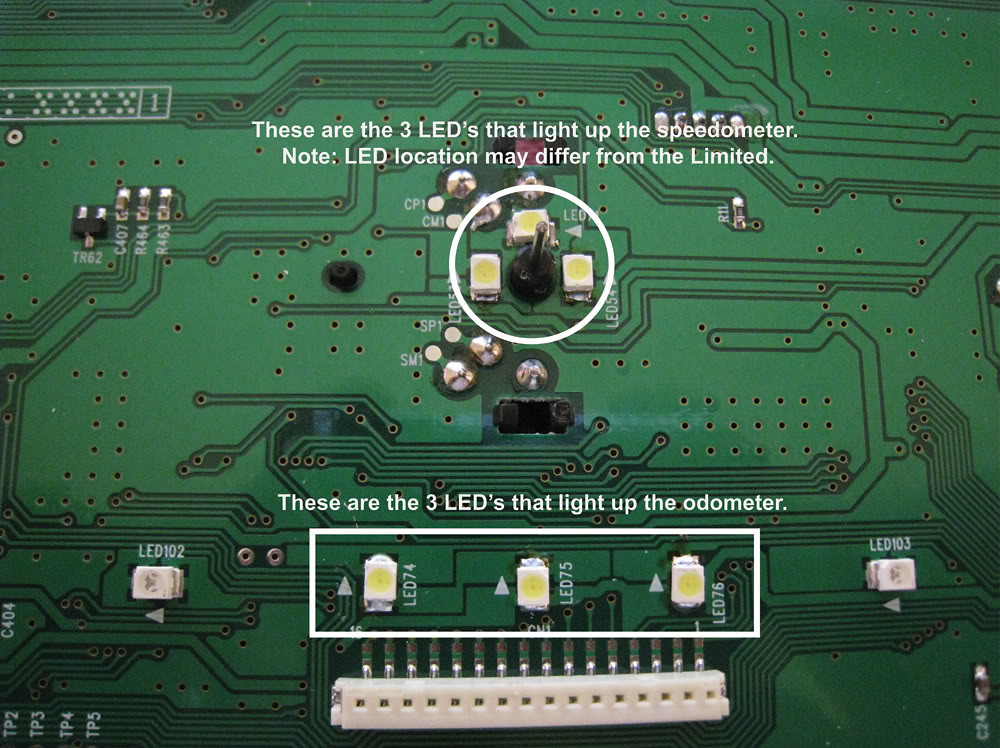
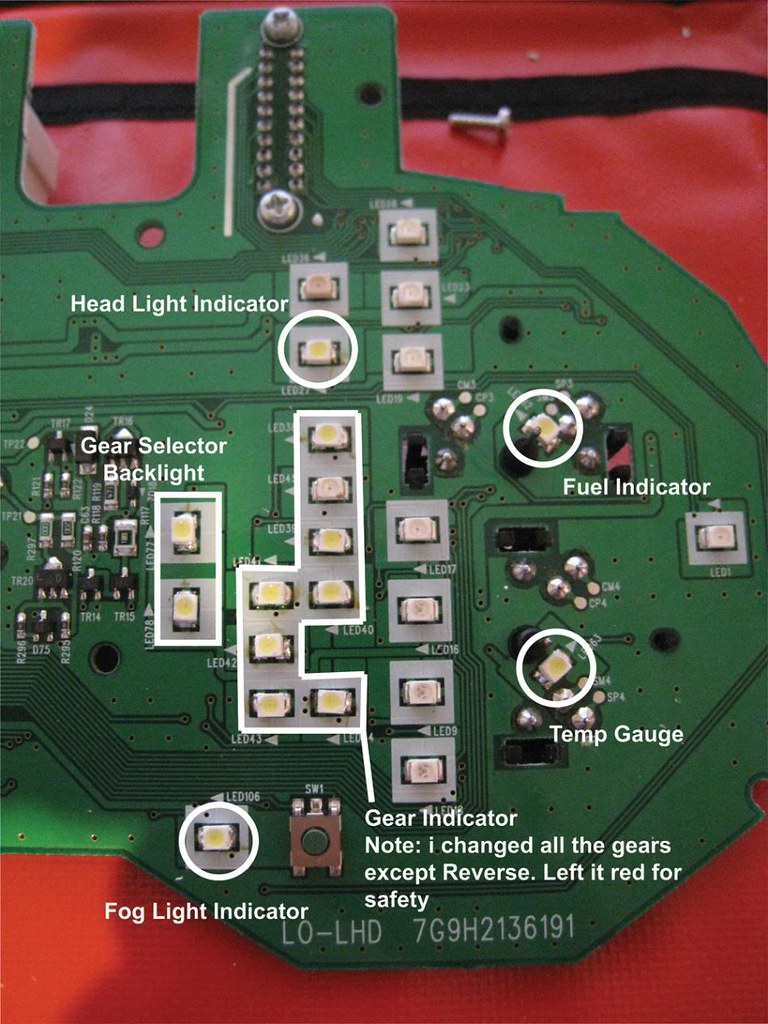
15 PLCC-2 Surface Mount SMT LEDs (2-RPM, 3-Speedometer, 3-odometer, 2-gear selector backlight, 1-Fuel, 1-temp, 3-steering wheel controls)
20-backlight only/16-indicators(1-rear window, 1*-4x4 switch, 1-Reset/Mode, 2-HVAC screen, 1-defrost, 1-recirculate, 1-fan speed, 1-A/C, 1-Fan location, 1-cup holder, 1-gear selector, 1-DAC, 1-window, 1-Air bag, 1-Passenger indicator, 1 or 2-115V, 1-RSCA off, 1-VSC, 1-Diff lock)

Useful links:
<a href="http://www.castulucci.com/projects/carpc/oemnaviaccess/">Remove lower dash, center console and HVAC unit</a>
<a href="http://www.toyotanation.com/forum/showthread.php?t=225203">Detailed how-to to swap Steering wheel control LED's</a>. I won't go over this since slvrAZtaco's write-up is thorough.

<B>Cluster LED Swap</B>

1) disconnect battery using the 10mm socket
2) Remove lower driver side dash and let it hang (Step 3 - <a href="http://www.castulucci.com/projects/carpc/oemnaviaccess/">How to Remove the Navigation Head Unit from a 2003 Toyota 4Runner)</a>
- While you have it disconnected, you can pull all the switches located on this panel
3) Grab the trim surrounding the gauge cluster near the bottom and pull towards you. Clips are the only thing holding it in place.
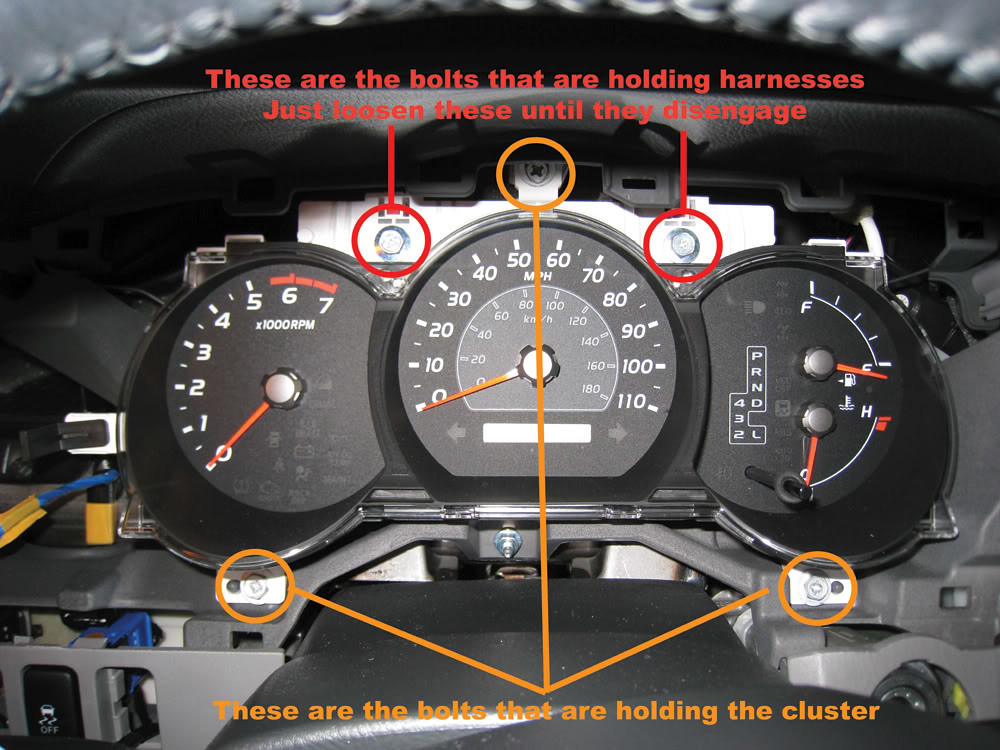
4) There are 3 screws/10mm bolts holding the gauge cluster and 2 bolts connecting the harnesses.
35851323765_2a8d832432_b.jpg


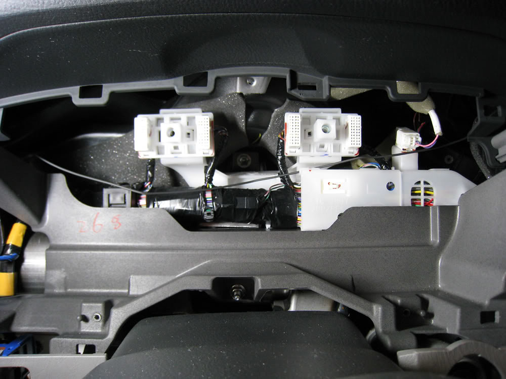
This is what's behind the cluster
35851323505_3832b19cf6_b.jpg

5) Remove the clear lens and interior black trim. both pieces are held on by plastic tabs.
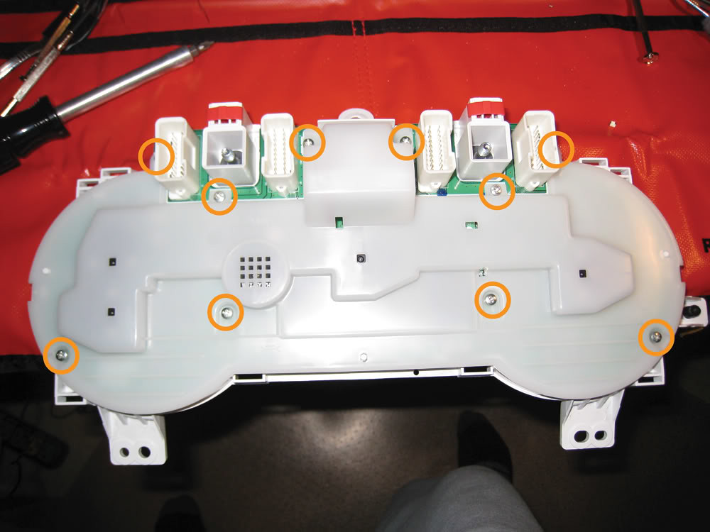
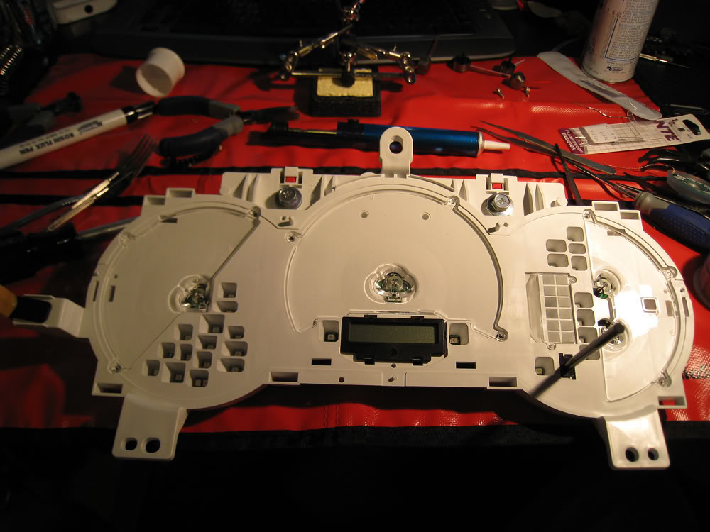
6) Remove white plastic backing
35810761656_09ec22d4ff_b.jpg


7) Take pictures of the needle positions at rest. It’s very important to keep the gauges accurate throughout.
8) Use the fork to lift the needle off the metal shaft safely. I found the fork is able to lift the needle while keeping it level and it will prevent you from accidentally twisting the needle during removal
35682256562_369c237439_b.jpg


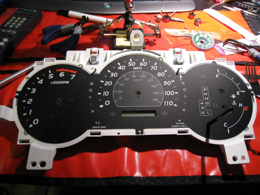
9) Remove the gauge face and reveal the white base with the plastic light distribution lens
35682256412_435dc8fa33_b.jpg


10) Take care when you are removing the odometer LCD. When you separate the white base and the PCB, do it evenly so you won't damage the prongs.
35682256332_90f3c523af_b.jpg


35851323115_a43db300b9_b.jpg


35682256042_c8556e14fd_b.jpg


Note:
- i found it easy to melt one side and carefully lift up that edge just enough to disengage. Then melt the other side to remove with tweezers.
- make sure you clean all old solder off the pads using the wick or solder sucker
- flux each pad
- Tin the pads
- The notch on the LED is the cathode. On the cluster, it has arrows to identify the direction you should place the LED.
- make sure you clean any extra flux off the PCB by using the contact cleaner sprayed on a q-tip after you attach the LED.

Pay close attention to the LCD odometer. Make sure you don't get any fingerprints on the leads or bend the leads when re-inserting the LCD into the PCB.
Once you're done, reassemble in reverse order.


Can you change the color of the indicator needles?
 

Members online

Forum statistics

Threads
278,316
Messages
3,554,120
Members
248,016
Latest member
Advally Service

Trending content

Back
Top