Ruby Tuesday - rad4runner's Mods and Restoration

Hi KidV ...
Interesting...
I have a basic manual transmission. Yes, bracket for clutch slave cylinder shares bottom mounting bolt, but nothing gets in the way.
Could you be referring to a truck with the upgraded dual-transfer case? maybe my truck is missing something there? LOL!

Nope, no duals here (yet). Maybe it was the combination of shock tower and clutch lines that gave me such grief, but when I did the starter and fuel filter on my current truck I had to struggle to get sockets on nuts. I think I used every wobble and extension in my toolbox.

I never did put the fuel filter back, it lived on my fender after that. :)
 
How Rear Window Control Works

Rear Window/Wiper Relay is behind panel near driver side seatbealt mechanism here:
rad4runner-albums-rear+window+control+mod-picture26042-rear-power-window-relay.jpg~original


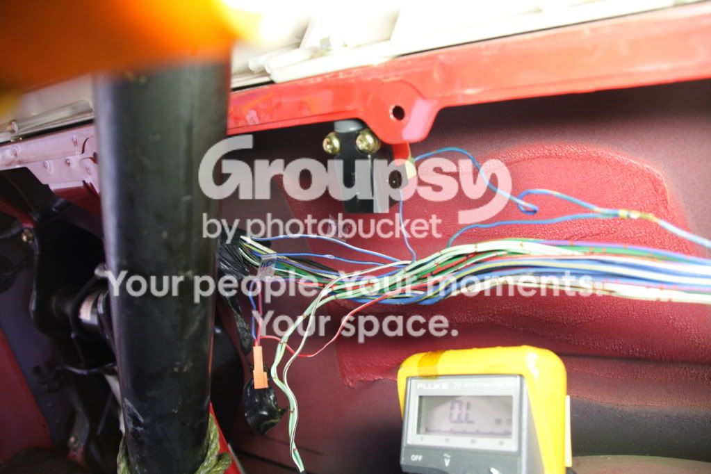
Relevant wiring runs behind panel near left side of rollbar here:
rad4runner-albums-rear+window+control+mod-picture25617-20120819-013.jpg~original


Top Off Switch is also there.
Cover_Top_Bolt_B_zps6916ddb6.jpg~original


Connector for Rear Window & Wiper Relay here:
rad4runner-albums-rear+window+control+mod-picture25616-20120819-009.jpg~original

Up-Down pins to use so you would not need ignition to be on are pins 11 & 12

Check against schematic here:

Rear_Window-Copy_zpsb4d9f347.jpg~original


Pin Numbering here:
rad4runner-albums-rear+window+control+mod-picture25615-electrical-piins.jpg~original


Location of Circuit breaker here:
003B_Fuse_Relay_Panel_0001-Copy_zpsc1e9e2f5.jpg~original


How backdoor window control switch (aka key switch) works:
Wire to pin 11 (light blue-white stripe) when connected to ground (via terminal 3 of top-off switch) will lower window.
Wire to pin 12 (lt blue-blk stripe) when connected to ground (via terminal 3 of top-off switch) will raise window.
(To test relay function, touching directly to chassis ground will work regardless of state of top off switch)

Console switch Operation:
Connecting wire going to pin 4 (Green with yel stripe) to ground (via window Down button, door lock button, top-off switch, and rear door clock switch) will lower window,
Connecting Pin5 to ground (Red yellow stripe) in same manner as above will raise it.

To test relay function (see schematic), assuming it has power, bypass up/down switch, door lock switch, top-off switch,a nd rear door lock detect switch:
Jump one of the pins above at a time, directly to ground and see if relay produces proper out voltage and polarity at pins 1 & 3

 
Last edited:
Sound-Deadening / Sound-Proofing Project Part 1

Posting in 3 parts because forum allows only 20 pics to a post...

MATERIALS:
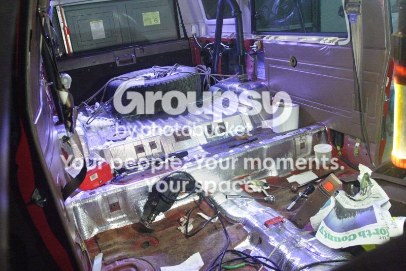
  • Peel and Seal for sound-deadening. Adding mass to panel minimizes tendency to vibrate and sound like a tin can. Five 6"x25' Rolls @$16.42 each from Lowes. Enough to cover all but the areas that already have original tar vibration deadener.
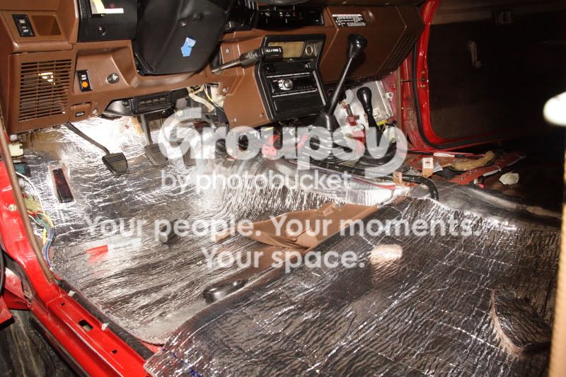
  • Thermoshield for thermal insulation from driver side firewall to left half of passenger floor (exhaust runs below this), passenger side firewall to front floor. Around $35 from Pep Boys. Thanks, Chefyota@Yotatech, for the tip.
  • Best Step Anti-fatigue mat primarily for insulation and cushioning on rear deck. @$22 from Sears. Remaining material was used from under front seat to under rear seat.
  • Yoga/exercise mat (3/8-inch thick) for lots of sound insulation where thicker is OK. From Big Lots, @$15 approx 30" x 72".
  • General purpose spray adhesive, approx $10 from Home Depot. Used sparingly and only where necessary.
  • Ensolite from RAAMMAt, for insulating where there's not much room for additional thickness. 36 inches x 56 inches. 2 pieces of plain (glue-on), and 2 pieces of peel & stick version. (Only 3 pieces would have been enough, but oh well...) Total $78.

Lowe.jpg~original

002_ThermoShield_Chef.jpg~original

003_bestStep_anti-fatigueMat.jpg~original


Rear Deck, Side Panels, Doors and Tailgate do not have any sound-dampening treatment at all...
005.jpg~original

I peeled and sealed all accessible panels, except for floor where there is already stock vibration deadener.
011_ALL.jpg~original

P_S001_zpsf1431a10.jpg~original


REAR DECK APPLICATION:
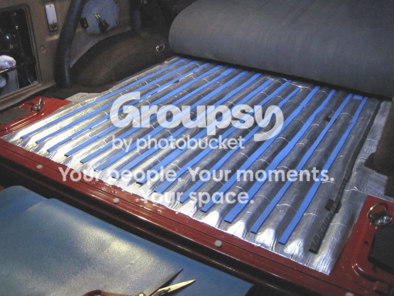
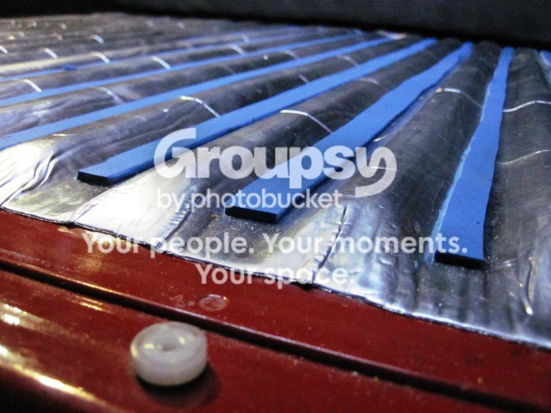
Applied P&S & built up the valleys with some rubbery material I happened to have. Remnants of the anti-fatigue mat above would work, too.
050.jpg~original

051.jpg~original


Trimmed anti-fatigue mat to fit around wheelwell, and tie-downs:
060.jpg~original

061.jpg~original

070.jpg~original

071.jpg~original

072.jpg~original

Got idea from Chef who has an SR5 to secure carpet to expansion nuts.
074.jpg~original


DRIVER'S SIDE
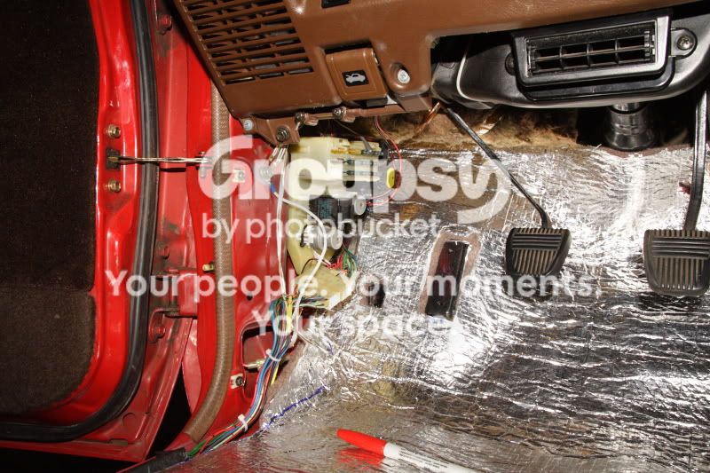
Kept stock vibration-damping material. Used remnants of Thermo-Shield to build up valleys. Here you'll also see P&S on tranny hump and double-layer on accessible areas of firewall.
000.jpg~original


Applied Thermo-shield from firewall all the way back to passenger floor. Exhaust pipe is below all that.
20121103_012.jpg~original


I would eventually fine-trim around kick panel. Still need to modify footrest to fit all that added thickness.
20121103_015.jpg~original


Next layer is 3/8-inch thick exercise mat as high as I could access on firewall. Seemed a better acoustic insulating material than the anti-fatigue mat. I initially calculated to put Ensolite here but turned out it was not needed anymore; Ensolite's benefit would be insignificant compared to this 3/8" think foam.
20121107_014.jpg~original


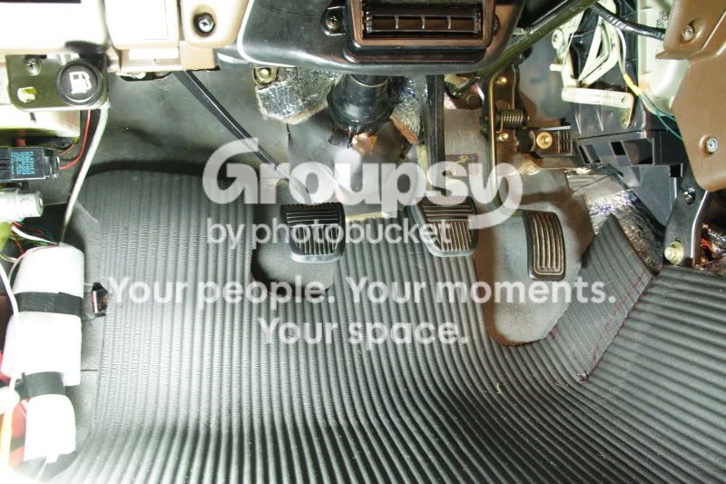
Needed cut-outs to clear clutch and gas pedal travels.
20121107_015.jpg~original


Carpet back on:
20121107_035.jpg~original
 
Last edited:
Sound-Deadening / Sound-Proofing Project Part 2

LEFT-REAR PASSENGER SECTION
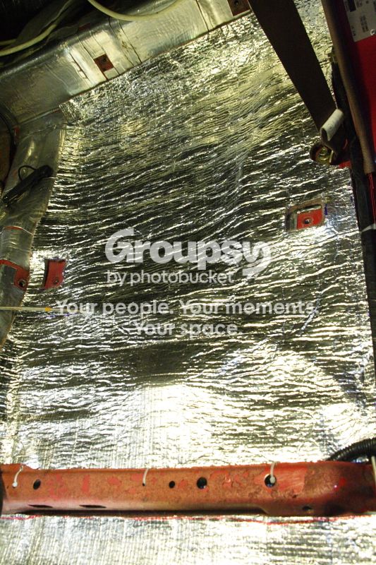
This is above the exhaust so Thermo-Shield was needed:
010.jpg~original

There was a little dip and I happened to have packaging foam sitting around so why not put extra insulation?
020.jpg~original


Anti-fatigue mat.
030.jpg~original


Plenty of room to build thickness so original carpet padding came back.
040-1.jpg~original


Carpet back:
060-1.jpg~original


FRONT PASSENGER

Thermo-Shield up to accessible areas on firewall:
20121104_012.jpg~original


Exercise Mat to tame the "purr of the 22R-E" :)
20121107_034.jpg~original


TRANSMISSION HUMP/CONSOLE:

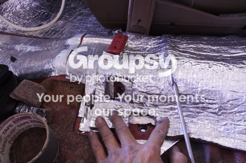
Peel & Seal applied then Themo Shield:

Traced out cut-outs for shift lever cover:
010-1.jpg~original

030-1.jpg~original


Thermo Shield on the rest of hump:
040.jpg~original


Then anti-fatigue mat on:
20121107_026.jpg~original

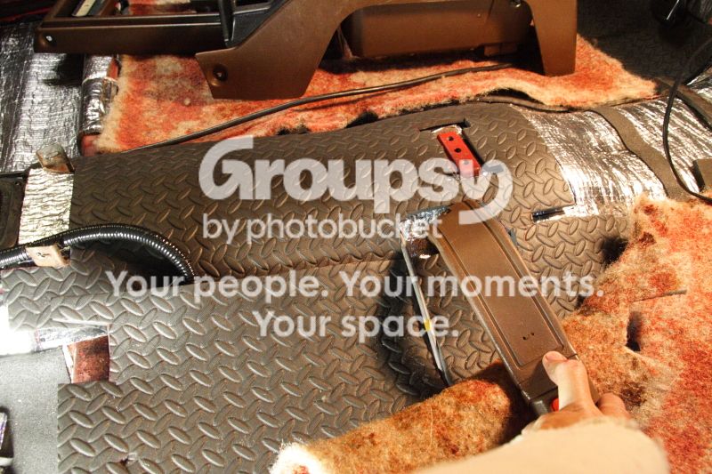
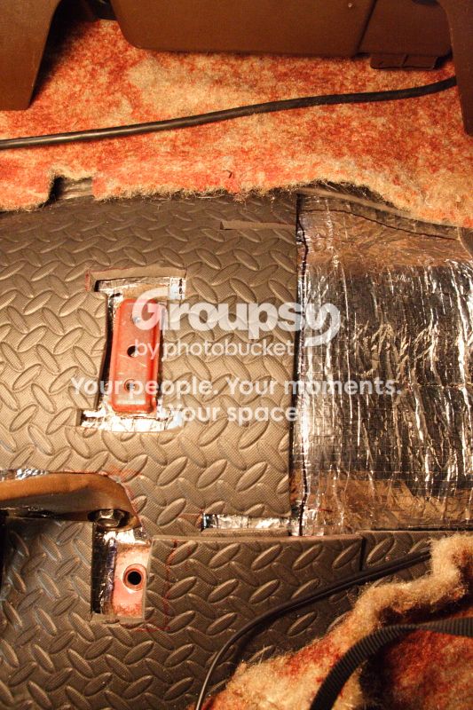
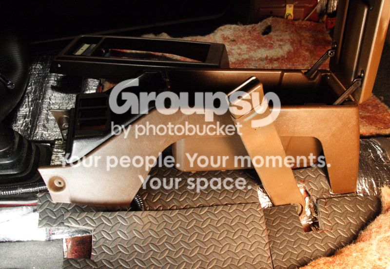
Anti-fatigue mat has clearance openings to minimize bulk and accommodate console & seatbelt where necessary:

Flexible conduit on left protects wiring for relocated console switches.

20121107_028.jpg~original

20121107_032.jpg~original

20121107_024.jpg~original


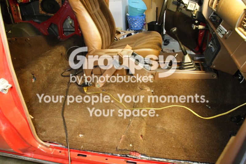
Carpet back:
002.jpg~original
 
Last edited:
Sound-Deadening / Sound-Proofing Project Part 3

SIDE PANELS / SPEAKERS
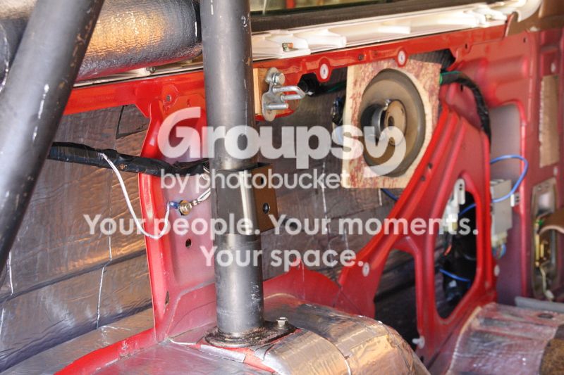
Peeled & Sealed side panels. Note that later, I would relocate harness so it is completely behind columns (insteadof zig-zagging in front and behind columns) to simplify future work on panels.
P_S002_zpsc98d2569.jpg~original

Before (Harness snakes to front and behind columns):
001-1.jpg~original

After (harness now behind columns):
006-1.jpg~original

006.jpg~original

Ground points also relocated to behind the columns. Nut sanded down to bare metal is seen here through my inspection mirror:
007.jpg~original

My inspection mirror:
008.jpg~original

Correct, I am not insecure =D

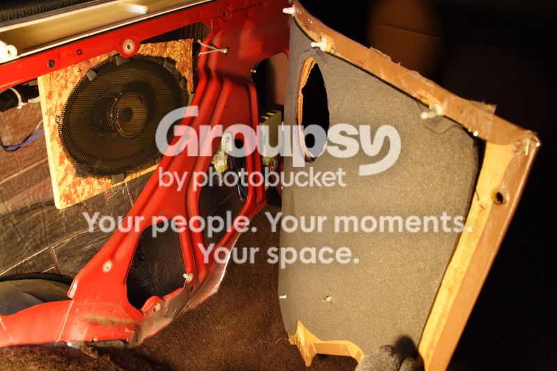
Also relocated 6x9 speakers to side of rear seats:
Speaker is mounted behind the particle board "ring". Grill mesh that came with speaker covers it.
Opening is sized and centered for 6.5-inch woofer so it's flexible. No need to open up completely for oval. (Oval woofer is worn out. Haven't decided what replacement to use, yet). What matters most is the tweeter is completely exposed, and most of the speaker cone faces free air. I'll make that pretty later.
002-2.jpg~original

I had enough of the RAAMAudio Ensolite so I applied to back of the side panels.
20121112_011.jpg~original

20121112_013.jpg~original
 
Last edited:
Hey! Thnx for all your posts. So i'm following the rear window switch mod. I've got it all wired in, but: I'm not sure what to do with the centre wire off the switch.
I'm using a window switch from another 4runner, so its an SPDT switch. I've attached the up (red w stripe) and down (red w another stripe) to the corresponding blue wired off the relay (#12 &11). The switch has what I'm assuming are grounds coming off both the up and down, so I've grounded those to the chassis.
Now, where do I put the centre wire?! Looking online seems to reveal that it goes above the relay, and you say to attach it to that crimp, but I don't see that crimp anywhere and I'm not sure what wire I should splice it to, if any.
Thanks...
 
Now, where do I put the centre wire?! ...I don't see that crimp anywhere and I'm not sure what wire I should splice it to, if any.
Thanks...

The center terminal goes to ground, via the Cover Top off switch.
Rear_Window_Control_From_Rear_Seatsa_zps9a0957c2.jpg~original


To find the crimp, you would need to strip the wrapping on the harness, just a forward of the cover top switch...
20120819_017.jpg~original
 
Ah. Well, in the process, two wires touched each other and fried the relay. Oops.
Now I'm trying to figure out how to jig this switch straight to the motor, bypassing the relay entirely.
I think I've got it: centre wire to battery, then one side to motor1 and ground respectively, and the other side to motor2 and ground respectively. Think that'll do the trick til I can get to my parts truck (and spare relay) next week? Wish I'd paid more attention during the electronics unit way back when.
Working up the gumption to go outside and try it: its -12'C up here, and we're leaving on a camping trip tomorrow...bout one hour of daylight left...guess I'm going outside now...
 
Last edited:
Ah. Well, in the process, two wires touched each other and fried the relay. Oops.
OH NO!

Now I'm trying to figure out how to jig this switch straight to the motor, bypassing the relay entirely.
I think I've got it: centre wire to battery, then one side to motor1 and ground respectively, and the other side to motor2 and ground respectively.

More OH NO! LOL!

I don't think that will work. The switches are simple command signal for relay to turn on power to the motor one way or the other. You should not run any of those switches directly to the battery. The only part of the up/down switches that really actually goes to the battery are the center positions. They eventually go to ground connected to battery negative.

You don't want to be experimenting now, especially in conditions you are in in - dark and cold and possible snowing :)

Instead, spend the time testing your relay. Very simple, especially if you know that all worked well before you tried the mod.

Leave everything stock,
Take a piece of wire about 2 feet,
Connect one end of wire to body ground,
Leave all window controls in neutral position (Neither up nor down),
Touch other end of wire to the up/down pins of the relay (see my schematic) one at a time (maybe with aid of a paper clip to reach inside the back of the connector)
Windows should roll up or down.
 
Putting Tire / Wheel Info in Plain View

Tire / Wheel Info in Plain View
No Guesswork: All necessary info handy...
KIMG0502-Copy_zps49fcf820.jpg~original
 
Alternator to Battery ("B") Wire Upgrade

I upgraded to 90-amp alternator. Here's the final schematic for upgraded "B" (alt-to-batt) wire... This setup addresses worst-case scenarios discussed on my earlier post.

20141215_Charging_Alt_Direct_To_Batt_zpsf7ba9fc5.jpg~original


I disconnected the stock "B" wire from this terminal post (below)...
002_B_Terminal_zps4b6e920f.jpg~original


I removed this disconnect that merely takes up space and is simply another potential place for corrosion to happen (pic here)...
95417291-cf16-4e1a-9936-7f4d622583e3_zpsf8501af4.jpg~original


... traced stock "B" wire all the way to the fuse block, and removed it. There are two other white wires (part of fuse block wiring), I re-connected them back to the screw terminal where the "B" cable was connected.

I then replaced the stock "B" wire with a single, continuous length of 6-AWG wire from NAPA, parallel crimped to 10-AWG fusible link from Summit Racing, then to battery. New "B" wire is protected with flex conduit from the alternator "B" post all the way to the battery connector.
KIMG0133_zps7c73eb1b.jpg~original


KIMG0132_zpsnw6aighm.jpg~original


Note that removing that disconnect and removing the entire stock "B" wire leaves everything cleaner and reclaims real estate (i.e., for future auxiliary circuits fuse block).
Before it was crowded here:
95417291-cf16-4e1a-9936-7f4d622583e3_zpsf8501af4.jpg~original


After... clean, available space and mounting for auxiliary fuse block:
KIMG0133_zps7c73eb1b.jpg~original


I also relocated this component (a capacitor? Screwed down with the bracket for ignitor coil) to a hole farther back (closer to clutch reservoir) to clear the space for future fuse block. Also note that I cleaned ground connection down to bare metal, then coated everything with dielectric grease to prevent future corrosion.
KIMG0135_zpskwfaaghw.jpg~original
 
Last edited:
How Turn Signals and Hazards Work

Posting this on my own thread so it's easy to find...

How Turn Signals and Hazards Work. Schematic is for 22RE but other years may be same.

Schematic is below but please ignore the red and orange notes - This is for the 1988 MoreFunner - wire colors may vary from other years, but system works same way

Hazards take power from Hazard/Horn fuse, so can come on even with ignition off.
Turn signals take power from engine fuse, so will work only when engine IGN is on.

When hazard is on, or when turn signal is on, either left or right, you should see steady voltage at pin 7. This power goes to Pin 3 of flasher. Flasher will click. You should get alternating on-off 12V at Pin 1 of relay (Green-White).

When turn signal is on flasher relay will click,
At Right turn, Contact TB is connected to TR. you get power at PIn 8 (Green-yellow)
At left turn, TB is connected to TL. YOu get 12V at Pin 9 (green-Black).

With hazards on,
Three bottom right contacts connect both left and side signals to pin 1 of flasher.

Marks_Engine_Fuse_TurnSignal-notes_zps8fa19fcf.jpg~original
 
Last edited:
IG2 Supplies Ignitor and Fuel Injector Resistors

Hi guys,
This is to answer a fellow member's question. Putting it here so it's easy for me to refer back to when needed.

The IG2 contacts of the ignition switch supplies power to the ignitor (both for 22R and 2RE engines), and the resistor network for the fuel injectors.

Ignitor Power Supply:
To 22R ignitor...
IG2_Ignitor_Injector_Power_Notes_zpscc3c1ca1.jpg~original


and also to 22RE Ignitor...
IG2_22RE_Ignitor_Injector_Power_02-_zps3f52a216.jpg~original


Fuel Injector Power Supply:
IG2_Injector_Power_zps054f05eb.jpg~original
 
Deleted Rod Antenna and Replaced with Hidden Antenna

Problem:
Non-power whip antenna gets in the way of loading 13-foot kayak on roof and is one more thing to worry about in the car wash. I do not want a power antenna because it's one more thing to break. I want minimal moving parts, simple, reliable, inexpensive - same reason I picked the 22RE MoreFunner.

Solution:
NOTE: NOT RECOMMENDED FOR TRUCKS WITH METAL ROOF. Metal roof will suppress radio signal

Got this Hidden Antenna from Amazon.

FM Reception was poor when antenna is placed on dash. AM reception; NADA. Too close to metal/ground, so...

I ran the cable through through the opening in body / pinchweld above the topliner near dome light...
KIMG0208_zps43af7590.jpg~original


Mounted on Fiberglas cap topliner (I will eventually move it so it is sandwiched between Fiberglas cap and topliner mat).
KIMG0216_zps20c72bfb.jpg~original

NOTE: NOT RECOMMENDED FOR TRUCKS WITH METAL ROOF. Metal roof will suppress radio signal.

Ran it in the channel above the door. I had to correct mistake I made of running it through opening where the rib goes in.
KIMG0215_zps86151e30.jpg~original


I added a 48-inch extension cable ($5.61 at OReillys) here...
KIMG0214_zps271368b0.jpg~original


Ran it inside the B-pillar to an opening behind the ECU, then eventually to the radio...

Results:
Good FM Reception, Decent AM reception.
No more antenna rod sticking out of the fender....
Antenna_Base_zps84f68ee6.jpg~original


If Anyone is interested in the stock antenna assembly, including the whip and cable, I'll sell it for $20 (local pick-up only). The mounting nut alone for the antenna base is $12 at the dealer.
 

Members online

Forum statistics

Threads
278,312
Messages
3,554,087
Members
248,016
Latest member
Advally Service

Trending content

Back
Top